RAIN RFID 101 for Label Converters – Webinar Recap
May 31, 2023
As the demand for RFID smart labels is growing, traditional label converters are increasingly getting questions from their customers about adding RFID to their label products.
Label converters that are just starting with RFID or considering it, need to first educate themselves on the fundamentals of the technology and what is involved in producing RFID labels. We decided to host a webinar to help with this first step.
Or read a summary of the main points below.
RFID Market is THE Market to Be In
The RAIN RFID market is developing in terms of volume, value, and diversity. Big retailer mandates, such as the Walmart mandate, also have an effect on driving growth on the retailer side, creating opportunities and challenges for the players in the market. Likely, your first RFID label customer will not be your last one.
The webinar focused on the basics of RAIN RFID specifically in the context of label converting in the retail industry: what are the key aspects that a label converter needs to consider when adding an RFID inlay into labels, turning them into RFID labels?
The webinar also touched on data standards and data encoding. Knowledge of encoding and different data standards is the key to preventing tag clutter which can be an issue in the RFID industry, but also to enabling the use of the item’s digital identity throughout its lifecycle. For example, the same RFID tag can potentially be used in various different applications from logistics management, and inventory tracking in the store, to customer self-checkout, and customer experience applications.
There are a lot of great resources available for the basics of RAIN RFID technology, its applications, and its unique benefits. If you are a RAIN RFID beginner, https://www.rainrfid.org is a great place to start.
How to Approach the Increased RFID Label Demand?
The typical steps that label converters need to take to get into the RFID label business include:
- Acquiring information and knowledge
- Expanding supplier and partner networks
- Upgrading different production machinery for RAIN RFID
- Investing in dedicated RAIN RFID production machinery
The first step always is to acquire information. What does your customer need and is there a mandate or any other requirements documentation that you need to familiarize yourself with? What is the format of the label that is needed; a sticker, a hangtag, or a prime label? What kind of data is needed for the label, both printed and encoded?
You will also need to learn essential information about RFID technology and RF-specific considerations for the label production process. Inhouse expertise on RFID and any applicable mandates is highly recommended, in addition to finding the right partners. An in-house expert enables you to become a value-added supplier to your customer to navigate through new requirements from their retail customer.
Read on to get started with the first step.
What do you need to know about RFID inlays?
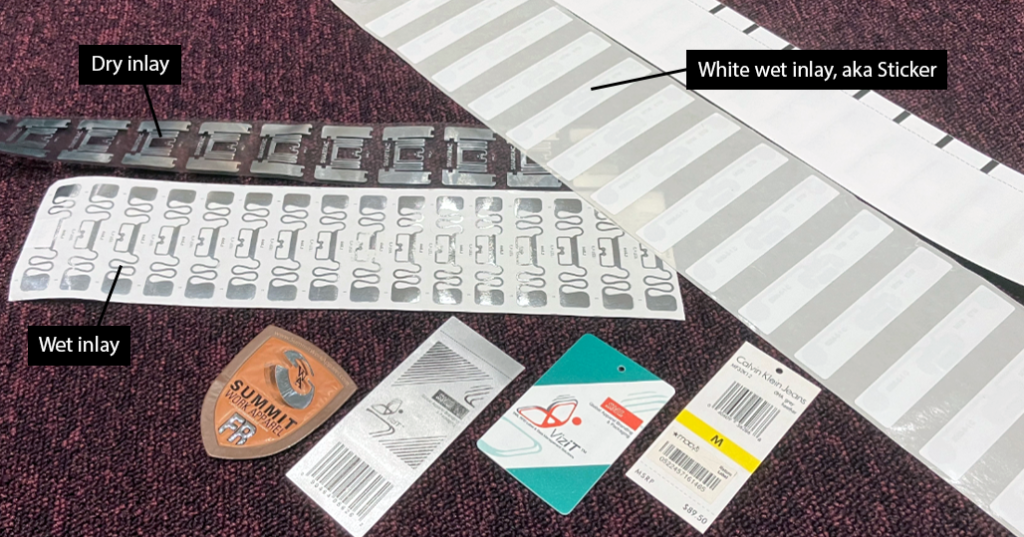
One of the core components of an RFID label is an inlay, which consists of an antenna on a substrate and an IC (chip) glued on top of the antenna. This process creates dry inlays. Dry inlays do not have an adhesive layer.
A term you often hear related to retail label mandates is white wet inlay, also known as a “sticker”. A sticker refers to a blank RFID inlay that has adhesive and liner layers and a simple white facestock. A sticker can be applied directly to an item.
- Dry inlays: no self-adhesive layer in the inlay. I.e. it is not a sticker
- Wet inlays: an inlay in a sticker format with an adhesive and liner layers, and it can be directly applied on top of an item without additional converting process
- White we inlay aka Sticker: an inlay in a sticker format with adhesive and liner layers, and a white facestock
Overview of the RFID Manufacturing Process
RFID label converting includes unique requirements and considerations for the converting process. Before going into the converting process, it is essential to have at least a high-level understanding of the entire RFID manufacturing process and how converting relates to the process.
- Without going into component manufacturing (IC, antenna, liner materials, etc.) the first step in the process is chip attachment (aka IC bonding) where the IC is attached to an antenna to form an uncut dry inlay. There are specialized manufacturing companies that focus on IC attachment to produce inlays.
- Next, the uncut dry inlays are converted in one or more process steps into labels: material layers, and adhesives are added, and labels are cut into white labels, aka stickers. This simplified process is just one option and there are a lot of different processes for RFID label converting, depending on the type of label and use case.
- After converting, data needs to be added to the blank label. This process is called personalization and can sometimes be done on the same label-converting line. Data is encoded into the labels to give them a unique serial number that can be read with RAIN RFID readers. Personalization also includes printing human-readable data and information on labels.
The last step of the process is attaching the ready label to an item, and turning it into a tagged item.
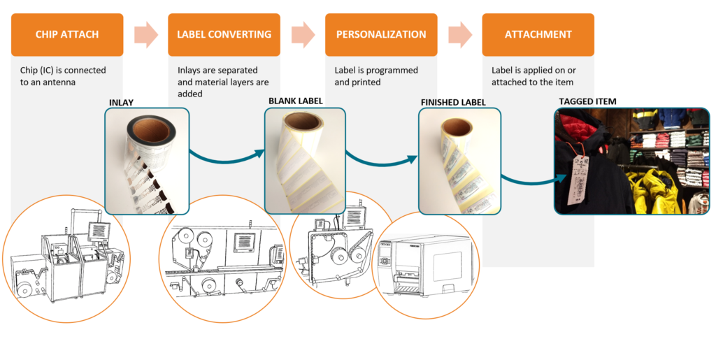
For a converting company, the business opportunity is anywhere between dry-cut inlays and personalization. This strategic decision impacts the label manufacturing process changes and machinery investments that are needed.
Retail RFID Mandate Data Terminology
One of the growth drivers for RFID labels is coming from the big retailers mandating the use of RFID for their suppliers. There are some basic terms you need to be aware of, specifically related to the retail mandate landscape.
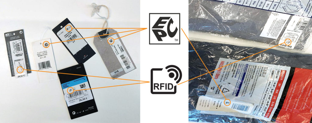
When your existing customer is asking for RFID labels for item identification, in terms of data, you will need to convert the products’ UPC / EAN / GTIN barcode number to an RFID encoding and add a serial number. The combination (barcode number + serial number) is a unique EPC, which is the GS1 term for an RFID-encoded number and stands for Electronic Product Code.
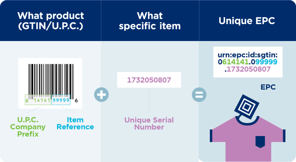
The retail world has traditionally focused on using barcodes to identify the product type (stock keeping unit, aka SKU), for example, a 5 lb bag of flour or a 1 gallon of milk. This is now changing into having a unique identifier for every single item. By adding a serial number to the product label, you don’t just know the product type, but exactly which individual product package it is. This naturally requires that every single serial number is unique. You should always use official RFID tag data standards/numbering schemes.
One term that comes across in the retail mandates is “permalock”. Permalocking the encoded RFID data means that users cannot change the data. RFID tag data can also be “locked”, but locked data can be re-written with a password. Permalocking the tag data is required in most retail mandates.
- UPC = EAN = GTIN = barcode number
- EPC = GS1 term for RFID-encoded number
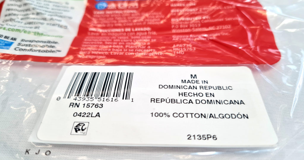
- EPC or ISO RFID logo is usually required to be printed on the labels to indicate to consumers that the label includes an RFID tag
- SGTIN-96 = Encoding scheme that includes GTIN and the serial number. The number 96 refers to the number of bits in the tag chip where the information is encoded
- Permalock = RFID encoded data is permanently locked so that users cannot change (re-write) the data
How to Get Started
In short, you can get started with the following steps
- Source inlays
- Get machinery to insert/laminate RFID inlay on a sticker or a prime label
- Add quality control
- Find out if encoding is required. If yes, get encoding equipment and data models
Inlay Selection
In some cases, the mandate specifies the type of inlays that can be used. If the inlays are not specified by mandates, often there are de-facto inlays that are being used in particular industries and applications. Inlays specified in the mandates are selected through quality certification processes.
Auburn University ARC certification program works closely with big retailers to establish quality standards and performance requirements for inlays in various applications and environments. Those requirements are defined in requirement Specs maintained by ARC. The ARC program tests inlays against the requirements in the Spec, defining and listing which inlays are approved for that Spec.
Retailers can check which inlay Spec applies to different product categories and which inlays are approved to meet the performance requirements for that Spec.
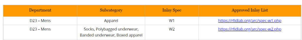
However, not all retailers use the ARC specifications. Some have in-house specifications and documentation that specify which inlays are accepted.
Most mandates define the dimensions of the finalized RFID labels and specify the performance of the inlays by referring to the ARC categories. Typically there are multiple options for inlays that meet the requirements available. An important consideration is to take the converting machine capabilities into account;
- what size rolls can be used in the machine,
- what should the roll core diameter be,
- should the inlays be cut or uncut,
- do you need dry or wet inlays, etc?
These practical considerations may limit the selection of possible inlays and their delivery format.
Other considerations for inlay sourcing may include pricing, delivery terms, and schedules, support availability from the inlay supplier, available quality data of the inlays, etc.
- Download the RAIN RFID Tag Buyer’s Guide to learn what to ask from the tag suppliers and what specifications should you consider to make better decisions with tag selection.
Label Approval
Next, you need to figure out the label type required by your customer. There are different types of RFID labels, prime labels, hang tags, and stickers. RFID tags can also be embedded into the product or packaging. In retail, a sticker, which is an RFID label with a simple white facestock, has become a common way to add RFID to products. The retail mandates may also define requirements for the sticker facestock and adhesive materials.
Next, your customer needs to have the finished label go through an approval process in which the retailer can verify that the labels are encoded properly, contain all the required printed information, and are positioned properly on the product. Auburn University’s ARC program covers the label approval process for most retailers. Not all retailers go through the ARC program, however, they may also have their own internal approval process.
Another term you may run into is GS1 TIPP, which stands for Tagged Item Performance Protocol. In the TIPP approach, instead of testing tags or inlays, the testing is done with the item that is already tagged with RFID. TIPP is used for some mandates in Europe and its use is also increasing in North America, especially for the use of food and pharmaceuticals.
RAIN RFID Production Machinery – Upgrade or invest in new?
RFID inlays are a layer of materials. If a converting machine has an insertion capability or a laminating capability and a die-cut station, those machines can typically also be used for inserting RFID inlays. But there are a few considerations to keep in mind.
For dry inlays that don’t have any material on top of the IC, ESD (electrostatic discharge) protection and tension control should be considered. A common reason for IC malfunction is either too loose or too high tension for the inlay roll. If the roll is too loose, it can slip and break off the IC. If the roll is too tight and there is too much tension, it may crack the IC or IC connection. A proper quality control system is the only way to know if something is going wrong in the process. Real-time visibility of each label’s performance allows adjusting the process parameters as soon as problems are detected, eliminating waste and re-runs. If a machine has some kind of tension control or some kind of ESD protection, typically that also works for RFID. Wet inlays with material protecting the IC and antenna, are well protected against tension and ESD.
The other option is to invest in new RFID-specialized converting machines. This may become an option to consider as you grow your customer base and you need to scale the production. The good news is that there are options and expertise available to help you with your choices.
- Need help with your RFID opportunities and challenges? Contact us ›
Add Quality Control
Inlays are not continuous material, which makes position control critical. The inlay must be in a consistent position inside the label, and must not be cut or perforated.
Quality control for RFID labels differs greatly from quality control for traditional labels. Unlike barcodes, which can be verified and checked visually, RF performance cannot be seen. An RFID label that works well usually looks exactly like a label that does not work as specified.
The RF performance of the label needs to be tested to make sure it works within set performance requirements. An RFID tag may be readable, but the performance may not be good enough causing variation in the read range that is not acceptable for the intended use case. Read range is the distance that a tag can be detected with a reader. In other words, a tag may be readable in the production line in close proximity, but may not work when attached to an item and read with a handheld reader from a few meters apart in an inventory count.
Monitoring the performance of the tags is not complicated. It can be done in the production line at full production speeds, checking that every label on the line meets the specified performance requirements. The quality testing system brings visibility into the process, making sure you also catch any issues early on in the production run.
Encoding Equipment
RFID labels can be encoded either inline with encoding equipment integrated into the converting machine, with specialized roll-to-roll encoding machines, or using RFID printers. For large volumes, the ideal would be to encode inline and at high speed. RFID printers can be used as a temporary solution for larger volumes, short-run service bureau jobs and for low- to mid-volume stickers and prime labels that can be accommodated in a printer.
Stay Tuned for the Next Webinar
If you made it through to the end of this post, you might be interested to hear that we are planning a follow-up webinar that will dive deeper into the RFID label converting process. You can help us plan the content and make it more relevant to your needs by sending over any questions or suggestions related to the topic. (email: marketing@voyantic.com)
And make sure you’ll get the webinar invitation by signing up for our email updates →