Figuring out RAIN RFID and NFC tag design is not an easy task. All stages of the RFID tag design process are important to understand, from studying IC functionalities and selecting materials for tags, to design verification, tag selection, and documenting tag performance.
This page has an overview of everything you need to know about the tag design process.

1. Tag structure
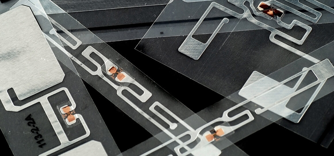
Both RAIN RFID and NFC tags’ IC is connected to an antenna and base material forming an inlay. The inlay is then packed to form different end products.

The IC, also known as ‘chip’, defines the memory and communication features of the tag. The antenna design defines the RF performance of the tag. The base material and packaging define the physical characteristics of the tag, for example, size and durability.
2. Tag design process
Both RAIN RFID and NFC tag design includes the following steps. The process is linear in principle, but iterations are typically needed for perfecting the design.

With automated tools, the design cycle time from antenna design to prototyping and design verification can take as little as 15 minutes.
2.1 Specifications & requirements
The design process starts with gathering requirements and defining the RFID tag specification. The requirements include elements about
- performance (read range, read angles, tuning)
- quality
- data content
- physical appearance.
Methods used in describing the requirements are numerous. Below is an example of requirements concerning RF performance. In practice, the RF performance is about the read range of RFID tags.
The first step in the specification is case description. For example, we need to attach a tag to a shoebox, and we use the tags to do inventory counting of the shoes with handheld RFID readers.
The specification can be analyzed and translated into the language of RF-engineering, to a technical specification such as: tag sensitivity must be better than -10 dBm; tag backscatter must be better than -30 dB; tag sensitivity and backscatter must meet the requirements at read angles of +/- 30 degrees from tag facing the reader antenna in aligned polarization; tag sensitivity and backscatter must meet the above requirements at frequencies from 890 MHz to 940 MHz when attached to cardboard.
And finally, the use case or technical specification may be translated to a user friendly and standardized format such as: tagged item must meet GS1 TIPP grade S05B.
Further reading
2.2 IC selection
IC selection is based partly on performance requirements and partly on data content requirements.
In many cases, the applications point towards certain standards and IC families. For example
- NFC tags according to ISO 15693 standard are common in library applications
- RAIN RFID tags according to EPC standard are used in inventory applications and in retail
- NFC tags according to ISO 14443A standards are common in ticketing applications
- RAIN RFID tags according to ISO standard are common in manufacturing, and so on.
It is good to keep in mind that there is always room for new innovative use cases. When making the choice between RAIN RFID or NFC, and which standards to use, the individual IC model can be selected. Tools like Voyantic Protocol Analyzer can be used for comparing and visualizing how RAIN RFID ICs operate.
2.3 Antenna design
Antenna design defines the RF performance of the tag:
- what is the expected reading distance
- what are the usable reading angles
- on which materials the tag works
- is the performance optimized for single tag reading or for tag populations.
The IC and selected standard pose some limitations to the performance. The first guess for the design can be created through antenna simulation tools, or by using an existing design as a starting point.
2.4 Prototyping
When a design is ready, a prototype needs to be assembled. For prototype antenna manufacturing there are different alternatives
- laser cutting tools,
- printing with conductive inks,
- etching the antenna to base material such as circuit board.
After the antenna is ready, the IC must be attached to the antenna, typically using an anisotropic glue.
2.5 Design verification
The prototype can be tested against the requirements with the Tagformance Pro system. In a few seconds the system shows in detail the tag’s
- tuning
- threshold sensitivity levels
- detuning on different materials
- read ranges in different read angles
- GS1 TIPP grades, and much more.
With detailed information, it is easy to adjust the antenna design and iterate until the requirements are met.
Further reading
- NFC Tapping – Smartphone Performance Comparison
- Radio Equipment Directive Safeguards RAIN RFID Users and Vendors
- Using Tagging Performance Specifications to Secure 100% Readability of RFID Enabled Tires
- RAIN RFID Tag Read Range: Opinion or Fact?
- How to Improve Efficiency of the R&D Team in UHF Tag Design
- The “Secret” to Ensuring Accuracy and Repeatability in RFID Testing – Properties of an RFID Test Chamber
2.6 Durability testing
In many applications the tag durability is important – how long time the tag is expected to stay functional when subjected to heat and cold, bending, occasional hits, and other conditions. Bendurance is a test system that can be used for defining the durability of a tag design.
Sample report could look like this:
None of the tags were completely damaged after 1000 rounds. After 1000 rounds
- 4 tags out of 79 tested (~5%) had an abnormal performance from the beginning, the performance degraded more during the testing.
- 46 out of 79 tags (~58%) were still working as well as in the beginning.
- 25 tags out of 79 tags (~37%) had decreased performance during the test. The tags didn’t become completely unresponsive, but performance degraded significantly from the baseline.
The most fragile part of the inlay is typically the adhesive joint between the rigid chip and the flexible antenna. When this joint is bent, typically the tag does not break at once, but gradually. Each bend creates micro-fractures to bonding adhesive and the fractures gradually decrease the tag performance.

2.7 Documenting
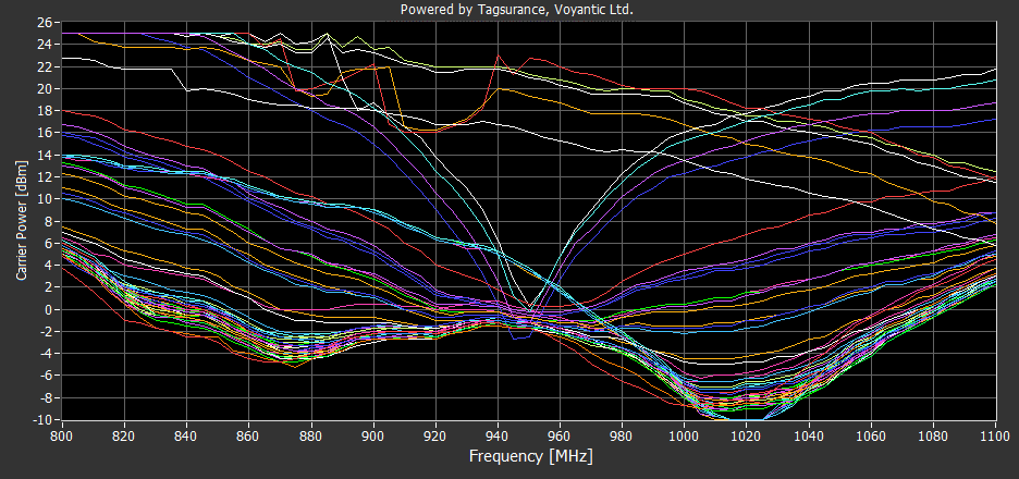
Customers and users are interested to know how the design tag works and how durable it is. The same test tools – Tagformance® Pro and Bendurance™ provide data for technical documentation. The threshold curves describing the tag tuning and read ranges, orientation patterns describing reading capability from different angles, and other information and graphs are a big part of data content customers are expecting to see of the tags.
Further reading
- How to win sales with good data
- View sample datasheet
- Wideband test results of tags
- Download sample test report in .tff format
3. Tag performance
There are differences between RFID tags. Some are designed to be cost-effective and versatile. Others are optimized for specific applications. How well a tag functions in a given application depends on the used IC, antenna, and matching circuit, as well as materials surrounding the tag, and other environmental factors.
The traditional approach in the RFID industry and academia is to look at the forward link and return link performance separately. The forward link is limited by power transfer to the tag; thus, the key performance parameter is tag sensitivity. The return link, in turn, is limited by detecting the signal scattering back from the tag; thus, the key performance parameter is the backscatter signal strength of the tag. These parameters are typically measured as a function of the carrier frequency, orientation angle, substrate, etc.
3.1 RAIN RFID tag performance
- tuning
- read range
- orientation
- tag populations
3.2 NFC tag performance
- tuning
- antenna vs tag – passive vs active
- magnetic field strength – coupling
4. Standards
Most of the RFID and NFC standards are about the data content and air interface between the tag and the reading device. Some standards give guidance also to tag design.
Retail and the retail supply chain are among the biggest users of UHF RFID technology. However, retail RFID projects are not the most simple ones. Items in retail come in all shapes, sizes, and materials. They are shipped in different boxes and stored and displayed on all kinds of racks, shelves, and tables. Also, different readers are used in different applications: logistics tracking, inventory count, RFID EAS, POS, and so on. GS1 Tagged-Item Performance Protocol [TIPP] was developed to help retail RFID by making buying and selling tags easier. TIPP translates complicated system-level requirements into simplified component level pass/fail verification that any vendor can handle themselves.
The purpose of the ARC program is to ensure that RFID tags are able to meet or exceed the levels of performance and quality necessary to provide benefit to the end-user in a consistent and cost-effective manner. The ARC testing methodology is open and has been established through industry collaboration. No vendor is excluded, and in order to remain abreast of technological developments, ongoing participation is encouraged. The methodology is clearly defined, but continual assessment and enhancement input into the testing process is encouraged and incorporated into evolving revisions (Auburn University RFID Lab, 2020).
- ISO 14443-a classifies NFC tags based on dimension
- GS1 TIPP is used to define RAIN RFID tags performance grades
- SAE AS5678B sets requirements for aerospace parts tagging
- ARC Program is used to certify tags meeting performance criteria set by users, mainly in US retail
- ETSI RED Emission testing is a European radio regulation that covers also passive UHF RFID (RAIN RFID) tags.
Further reading
- Using TIPP Tagged Item Performance Protocol Outside Retail
- GS1 Releases the TIPP Global Guideline – Streamlines RAIN RFID Adoption in Retail and Fosters Tagging Innovations
- TIPP Offers Both Low-Hanging Fruits and Long-Term Efficiencies for Everyone in the Retail Supply Chain
- Why RFID TIPP Grading is Great News for the Retailers Worldwide
- Tagged-Item Grading Helps Retail UHF RFID Projects