All blog posts

On-Demand Webinar – Achieving Excellence in RAIN RFID IC Attach Process

Feb 26, 2024

Recently, we had the pleasure of having James Guzzo from Impinj and Hannes Jehle from DELO present at our webinar on the intricacies of the RAIN RFID IC attach process. The webinar covered the numerous process variables that impact the quality and performance of the inlay, how IC manufacturing recipes can be used in the production process, and the critical role of process monitoring.

If you missed the webinar, the recording is available to view on-demand ›

Bonus Q&A – Questions Not Answered During the Live Session

The webinar topic proved to be a popular one. The presenters received so many questions during the webinar that the time ran out to cover all of them. So, we followed up with Hannes and James with a few of the questions that were not answered during the live session.

(I recommend you watch the webinar recording before reading the rest of this blog.)

Webinar Recording

Q1: How do we ensure the accuracy of IC positioning in the process?

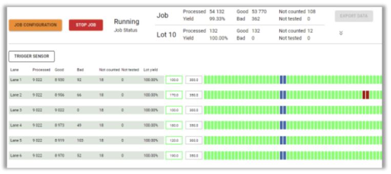
James Guzzo: The single biggest way that you can ensure the accuracy of the IC position is to turn on the DDA Vision system statistics (postplace.rep) and monitor the machine die ejection accuracy and adjust the DDA settings to improve the die ejection/placement accuracy if needed. There are two key parameters the DDA reports on which are the Y-offset (measured in microns) which is the shift up or down of the IC relative to the antenna gap. The second parameter is the die rotation left or right relative to a perfect alignment to the antenna gap (measured in degrees).

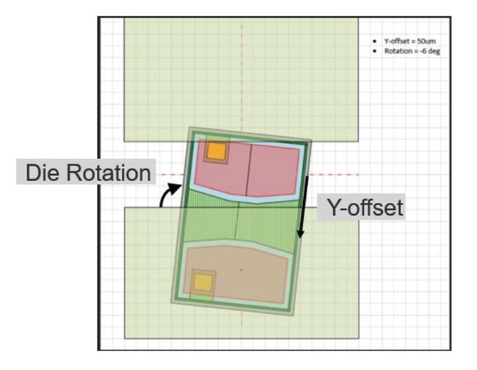
The Inlay assembly process allows for a certain level of inaccuracy in the Y-offset and Die rotation and will still produce a reliable, electrically well-performing inlay.  The amount of Y-offset and die rotation tolerable is a function of the actual measured (actual) antenna gap and the size of the IC and the size of the IC pads.

There is the possibility that the die can shift or spin in the epoxy dot post-vision system inspection, but we have found the dominant factor in die placement accuracy occurs during die ejection off of the tape.  The Voyantic Tagsuance inline electrical test yield generally correlates well with the postplace.rep placement accuracy.

Factors that impact the die placement accuracy and can be tuned to improve die placement: Die Ejector Needle Selection (needle tip radius and angle), dicing tape expansion, DDA die Ejection parameters(Cap Gap, Cap Retract, needle offset, vacuum delay,…)

Q2: Do you have any suggestions about the shape and also size of the die landing area? And what about the gap, previously you shoved 150um for the M800 series (talking about a “standard” antenna).

James Guzzo: See the response to Question 1 above for Context.

Ways to improve the maximum placement tolerance:  Reduce the actual antenna gap of your antenna design by reducing your drawn antenna gap. Previously most etched Al on PET inlay manufacturers allowed a minimum drawn 140um and the stated actual gap tolerance is +/-50ums to the drawn. However many manufacturers typically do better than this and are closer to a +40um/-30 based on sampling and measuring actual antenna gaps for several models of inlays.

Numerous etched Al antenna on PET manufacturers now allow a minimum drawn antenna gap of 110um-120um drawn gap and correspondingly are able to achieve actual(measured) antenna gaps of 130um – 160um depending upon the antenna layout and geometries.

Q3: There is much recent talk or hype of “trillions” of RAIN RFID inlays per year to be made, presumably requiring thousands of chip-attach machines. What is the hourly capacity of the highest-capacity IC placement machine?

James Guzzo: The current state-of-the-art direct die attach machine models can create 40k, 80k, and up to 100k inlays per hour.

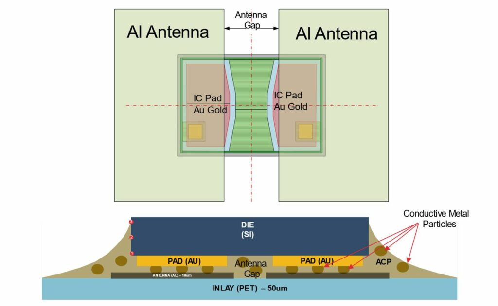
Q4: What is the allowed residue thickness between the gold pad and the aluminium for a proper connection – the thickness the gold particles can bridge?

James Guzzo: The electrical connection between the Tag ICs gold pads and the etched Aluminum Antenna Leads are actually made through the 3-8um diameter metal particles that are in the ACP (Anisotropic Conductive Paste). Different ACPs have different size particles of different conductive materials (e.g. tungsten, nickel, etc.) When the IC is bonded there are two hot pieces of metal in the Die attach machine (Called thermodes) that press against the back side of the die (from the top) and the bottom of the PET inlay. The thermodes accomplish 2 goals: The first is to push the conductive metal fragments into the gold pads and the Al antenna leads and the second goal is to cure or harden the Epoxy. One of the “Bonding” parameters is how much force the thermodes push the die into the inlay. The typical Thermode Bond Force is 1.5 Newtons to 2.5 Newtons.

Inlay bottom and cross-section view.

Q4: Are there any low or no-heat adhesives being developed to save time and increase system throughput?

Hannes Jehle: At the moment heat curing is the only curing technology which allows the required reliability. There is a special “low temperature curing” adhesive in our portfolio which allows curing temperatures of 150°C.

Q5: Where do you see the company Delo’s glues in comparison to other glue manufacturers in the race for market share with next-generation machines driving the bonding times lower and temperature higher to reduce machine footprint?

Hannes Jehle: Besides many other applications I do see DELO as the leading supplier for ACAs for RFID applications. Due to our very fast development cycles, outstanding lab support, and very close cooperation with our partners. As far as I know, there are none or not many other ACA manufacturers that can make curing speeds of <100ms happen.

Q6: In your pictures, there is a lot of epoxy placed for those M700 chips. How do you avoid the chips being pulled up by the bond tape in the final bonder?

Hannes Jehle: The coating of the bond tape prevents the tape itself from sticking to the die or epoxy.

Q7: What will happen to an RFID tag if the ACP is not fully cured? Or if the bonding force is not enough or too much?

Hannes Jehle: The required reliabilities will not be achieved. (THT, bending, die shear)

——————————————————————–

See you at our next webinar!

All blog posts
All blog posts

Lot Management in RFID Tag Production – Essential Machine Requirements

Feb 08, 2024

Over the past few years, Voyantic has successfully implemented the Tagsurance 3 quality control system across multiple RFID tag production lines. These integrations not only enable the highest standards in tag manufacturing but also shed light on the positive advancements within the RFID industry. One notable development is the growing synergy between lot management and quality control. For an RFID production manager or quality manager, understanding the quantity of perfectly functioning tags in a delivery is far more meaningful than just having a count and yield percentage.

Incorporating lot management is more straightforward and cost-effective when done in conjunction with the purchase of new production machinery, rather than attempting to implement it post-machine deployment on the factory floor.

What is lot management? 

Lot management revolves around the concept of a known quantity of deliverables from a specific process step. In the realm of RFID label production, a lot typically corresponds to one roll of labels.

A closely related term is “job.” A job refers to an operation dedicated to producing a specific type of product for a customer or an internal order. Importantly, the process and output remain consistent throughout a job, which may encompass one or multiple lots.

The terminology is easiest to explain with some pictures.

Relation of a lot to an order from a customer, and a job in production.
A lot is typically the same as a roll.

Before starting a job in the Tagsurance GUI, it is possible to define the lot. The lot definition includes details such as.

  • Are all tags counted, or just the good ones? 
  • Is counting across lanes, or on a single lane? 
  • Is the lot change marked with a cut mark?
  • What should the machine do when the lot is complete?

Lot management

In a typical production setup, where delivery and production are roll-based, lot management includes:

  • Producing rolls with the desired quantity of labels,
  • Understanding the quantity of tags within each roll, and
  • Generating and reporting relevant data for each lot (each roll)

Tagsurance 3 system role in lot management

Tagsurance 3 quality control system plays a pivotal role in the seamless lot management in RFID tag manufacturing. It employs a sophisticated approach to decide whether an individual tag should be counted in the production result set, leveraging comprehensive test data to ascertain the number of tags produced on each lane, differentiating between good and failed tags.

One of the distinctive features of the Tagsurance 3 quality control system is its granular understanding of the location of each tag on the production line. It precisely tracks the lane and the distance from a trigger sensor in millimeters, providing essential position information. This combination of counts and position data serves as the cornerstone for effective lot management.

Given that the Tagsurance 3 quality control system possesses a wealth of information, it becomes the logical and secure choice to entrust with lot management. An alternative approach could involve transmitting count and fail status information to other machine components, such as the machine PLC. However, this introduces unnecessary complexity and potential risks. In high-speed production lines, even a minimal delay in data transmission (from Tagsurance 3 to machine PLC) carries the risk of misaligning counts by a single tag.

The optimal and most efficient solution is allowing the Tagsurance 3 quality control system to take charge of lot management for the following reasons:

  1. Precise Quantity Tracking: Tagsurance 3 is equipped to accurately determine the number of tags in a roll.
  2. Comprehensive Reporting: Tagsurance 3 generates and reports relevant data for each lot, providing a comprehensive overview of passed or failed tags.

When the Tagsurance 3 system manages the production lot information, the risk of split-brain problems between different systems is eliminated. Additionally, Tagsurance 3 offers the flexibility to provide precisely timed signals before, on, or after lot completion, ensuring a smooth and synchronized production process. This level of integration not only enhances operational efficiency but also mitigates the potential risks associated with data transmission delays in a fast-paced manufacturing environment.

Cut mark

The cut mark serves as a practical tool in lot management, providing a visual demarcation between the end of one lot and the commencement of the next.

Cut marks indicated in Tagsurance 3.

Tagsurance 3 system seamlessly integrates with the manufacturing process, triggering the device responsible for creating cut marks. In many instances, the same device used for marking failed tags is employed for printing cut marks as well.

What does the machine need to handle?

While the Tagsurance 3 system handles various aspects of lot management, the tag manufacturing machine still plays a critical role, particularly in the precise execution of cutting tasks to create the desired rolls.

There are different ways to do this: 

  1. Automatic turret rewinders 

Some machines incorporate automatic turret rewinders, presenting an efficient solution. In this setup, the production job operates continuously, and rolls are automatically cut to the correct size. This automation eliminates the need for manual roll changes by operators.

  1. Cut mark and manual cutting

In certain scenarios, manual or semi-manual cutting methods prove to be a better alternative. Safety considerations often drive this choice, as automatic cutters need to be well-shielded for the safety ofrom human operators.

In a manual or semi-manual process, the machine halts when the liner reaches the cut position, such as at a splicing table. The operator then manually cuts the liner before seamlessly continuing the process with a new output roll.

Please accept marketing cookies to watch this video.
This video shows an example of a Turret Rewinder by GM where, at the end of a lot, the machine first slows down and stops, and then an operator cuts the web and finally restarts the machine.

Selecting the appropriate cutting method depends on factors such as safety requirements and the layout of the roll handling area. Whether through automated turret rewinders or manual cutting processes, the tag manufacturing machine’s role in achieving precision and efficiency ensures the delivery of high-quality RFID tags.

Must-have machine features for seamless integration

One indispensable feature that facilitates the seamless integration of lot management with automated testing solutions is a digital IO (Input/Output) input, acting as a control mechanism for the manufacturing machine.

Stop signal input

For efficient lot management, there is a need for precise and controlled stopping mechanisms. Particularly in high-speed machines, abruptly halting operations may compromise accuracy, leading to challenges such as incorrect cutting positions on automatic turret rewinders or misalignment at the splicing table. The inclusion of a digital IO input allows for a controlled cessation of the machine, ensuring accuracy and reliability in the manufacturing process.

Slow down signal input

In practical terms, high-speed machines benefit from a gradual slowing down process before coming to a complete stop. This gradual deceleration is vital for intricate operations, such as ensuring precise cutting positions or accurate alignment at various stages of production. The machine’s ability to receive a digital IO input for initiating the slowdown process enhances the overall control and precision of the manufacturing workflow.

The machine slows down before stopping.

Serial port interface alternative for stop and slow down signals

While digital IO inputs serve as the standard for most machines, it’s worth noting exceptions, such as the utilization of a serial port interface in certain models like the Muhlbauer DDA machines. However, in general, the industry standard leans towards the effectiveness of digital IO inputs for optimal control and coordination between lot management and quality control systems.

Nice-to-have machine features for improved efficiency

Two features that significantly contribute to this efficiency are Cut Mark Capability and Operator Signal Integration.

Cut mark capability

Having a discernible cut mark on labels proves invaluable for human operators, especially when machine stopping accuracy is not within a few millimeters. This visual indicator aids operators in clearly identifying which labels belong to the previous lot and which are part of the next one. Even with automatic turret rewinders, the presence of a cut mark provides operators with peace of mind regarding the correctness of quantities.

The Tagsurance 3 system excels in this aspect, precisely triggering the cut mark at the right position. This feature not only enhances accuracy but also empowers operators with a clear demarcation between lots, ensuring seamless continuity in the production process.

Operator signal

Efficient lot management extends beyond just machine capabilities; it involves effective communication with operators. Even in the case of automatic turret rewinders or manual cutting scenarios, alerting operators when a lot is nearing completion proves invaluable. This proactive approach allows operators to prepare for tasks such as cutting the liner and changing the roll promptly, minimizing machine downtime.

The Tagsurance 3 system takes the lead by providing timely signals, either on lot completion or even a predetermined quantity before completion (e.g., 500 labels before the lot concludes). These signals can be utilized by the machine to trigger visual alerts, such as signal lights, or audible notifications through loudspeakers. This integrated communication ensures that operators are well-informed and can take prompt action, contributing to a more streamlined and efficient RFID tag manufacturing process.

Signal lights alert the machine operator.

Strategic considerations for a label manufacturer to optimize lot management

The seemingly minor features within the production machinery play a pivotal role in the seamless execution of lot management. Features such as

  • slow down signal input,
  • stop signal input,
  • serial port interface on some Muhlbauer DDA machines,
  • ability to print cut marks and,
  • ability to signal the operator

might appear subtle, but their absence can pose challenges in implementing effective lot management.

When investing in a new label manufacturing machine, ensure that lot management-related details are explicitly specified. The absence of connectors and signaling means can prevent lot management from working optimally. As RFID technology evolves, these features become indispensable for RFID production and quality managers seeking to elevate standards and achieve greater efficiency in the tag manufacturing process.

Connect with us to learn more about Tagsurance 3 lot management features and integration into production machines.

Request a Tagsurance 3 Demo

All blog posts
All blog posts

Employee Spotlight – Voyantic’s Solution Specialists

Feb 01, 2024

I talked with Voyantic’s Solution Specialists, Lasse Saarinen and Gerald Smid, about their work in the field with production testing clients. 

Voyantic provides quality testing systems for various label and tag production machines, for different stages in the production process. Although Tagsurance 3, our next-generation production testing system, is easy to integrate practically into any machine, there are always variables and machine features where our customer service team is needed to support the implementation and commissioning of the system. They are also at the forefront of demonstrating our system performance to prospective customers. 

Lasse Saarinen (left) and Gerald Smid help Voyantic’s customers in the field and online.

But what is it like to work in the field with Voyantic’s prospects and customers? To find out, I decided to talk with Voyantic’s Solution Specialists, Lasse Saarinen and Gerald Smid.

The role of Voyantic’s Solution Specialists is to support customers in finding the best solution for customers’ needs, integrating Voyantic systems, conducting product demonstrations, and providing training as needed. They are closely involved with both current and prospective customers. The job also involves a fair amount of travel to customer sites and various events.

– Voyantic is not just a “systems provider” but our customers receive assistance and support for system implementation, benefiting from our expertise and excellent customer service, explains Lasse.

– So, we provide solutions to our customers, summarizes Gerald.

And what does your work involve in practice?

– Typically, when a system is sold to a new customer we visit the customer on-site and ensure that the installations are working correctly. – On the second day, the customer does it themselves, and we are immediately available when questions arise.

– When the customer does it themselves, they learn the best. Soon, the customer’s questions become more detailed.

– After meeting face-to-face, it’s much easier to communicate both ways. We often have remote meetings in the demo room when demonstrating systems via camera. Video connection helps to some extent, but of course, it doesn’t replace being at the customer’s site for 2–3 days.

Who are the typical production testing customers and what challenges does Voyantic help to address? 

Typical customers for Voyantic’s production testing solution are either machine manufacturers who make production machines for different stages in the RFID label production process or companies that use the machines to make RFID inlays and finished labels. I asked Gerald and Lasse what are the machine types they see in the field.

-Machine manufacturers’ machine types include chip attachment machines, label converting machines, RFID inlay insertion machines, and different kinds of finishing and control machines where our RF quality testing system can be integrated, Lasse explains.

-Customers can also be broadly divided into those for whom RFID production is new and those who already produce RFID labels, Gerald defines. -One typical customer group, for example, includes label manufacturers. They receive requests from their customers to include RFID tags in labels and then try to figure out the best way to do it. This customer group naturally has many questions related to RFID technology in general.

– Another typical customer group is those already producing RFID labels with an existing, perhaps reader-based testing method. They might want to upgrade their system to a more comprehensive system.

– Many questions revolve around the installation of the testing system: How to integrate the system, and how quickly can the line run?

– A customer may have their own testing system. They can test to some extent whether the tags work but may not know if they meet the required quality standards.

– And if it’s a legacy testing system, the person who created the system may have retired, and no one else knows how to develop it. And there may not be spare parts available for the old system anymore.

Why is testing RFID labels so important?

It was mentioned that some customers may even have self-made testing systems. Why, for example, is a reader-based testing system not sufficient for an RFID label producer?

– Well, everyone knows the radio. We’re talking about frequencies. I could compare it to reader-based systems figuring out if the radio works. If something is heard, the radio works. In our system, using this analogy, in addition to hearing the radio, you identify different radio stations that are heard.

What are some tangible benefits of Voyantic’s testing system? 

– Consistency, both Lasse and Gerald agree.

– Rejecting tags that don’t meet the predefined performance requirements. 

– When the production output is consistent the read distance stays roughly the same in the end-use case. If there are deviations, it works less well. 

– Several meters of read distance may be lost with tags that are not consistent. If the tag is designed to be read from 3 meters away and doesn’t work, the system doesn’t recognize the product at all. That is why consistency is a vital element in RFID tag production.

– One reason for testing RFID tags is simply the quality requirements that many customers know to demand from the tags. 

– Quality test requirements also come from quality certifications. RFID tag production can be quality-certified, and there are test criteria that tags must meet to receive a certain certification. Then the tags must be tested in a specific way. The quality of the manufactured product must match the criteria.

What kind of classification are we talking about?

– The University of Auburn has the ARC program. Auburn’s ARC program has become a main quality certification for the RFID industry. It is the source of the criteria for testing.

– The need to prove quality is a basic requirement of any quality system, such as ISO 9001-based systems. These standards do not have detailed criteria for the testing, but some way to show the quality of the product is needed. We help tag manufacturers to use the quality control systems in a good way.

-The starting point is that if you want RFID on labels, it’s advisable to test them. Only through testing can any issues with the performance of the RFID label be identified before they go to customers.

– One feedback we have received from our customers after acquiring the systems is that when even one bad production lot is not delivered to the customer, the system has already paid for the investment, Gerald says.

– For future customers, we could encourage them by advising them to go ahead boldly. Our systems are surprisingly easy to use once you understand the concept, and you can always get help, the Voyantic Solution Specialists summarize.

All blog posts