RAIN RFID in Tool Management

Aug 06, 2020

中文版 Chinese version

Recent developments in RAIN RFID technology, markets, and global regulations have made the RAIN RFID an even more interesting technology. I believe that with the RAIN RFID a traditional industry such as tool manufacturing can join the digital revolution. In this blog, I will explain why it is a good time for the tool industry to adopt the RAIN RFID technology and how to get started.

RAIN is a brand name for passive UHF RFID technology based on GS1 EPC Gen2/ISO 18000-63 standard

RAIN Is Ready

In 2006, IR DSRC defeated RFID technology and was chosen for the Electronic Toll Collection (ETC) System in Taiwan’s freeways. Six years later, in 2012, Taiwan’s ETC system was migrated from IR DSRC to UHF RFID technology, which transferred the freeways tolling system from a flat-rate and barrier-based to a distance-based and multi-lane free-flow on all of Taiwan’s freeways. ETC application is an example of how the market will correct technology selection with time. The tool industry is now facing a similar choice as ETC in 2006. Let’s hope the right technology is chosen from the beginning.

I started to see some companies providing tool management solutions with UHF RFID technology back to 2010. Frankly speaking, I was in doubt at that time if the market would value such a solution. The cost of adding an RFID tag on each tool was not cheap. Also, having a tag recklessly attached or glued on tools seems inappropriate and not professional as the tag protruded on tools’ surface may affect the tool’s usage and cause potential danger to tool users. More importantly, I did not see UHF RFID was ready for tools management in terms of technology maturity then.

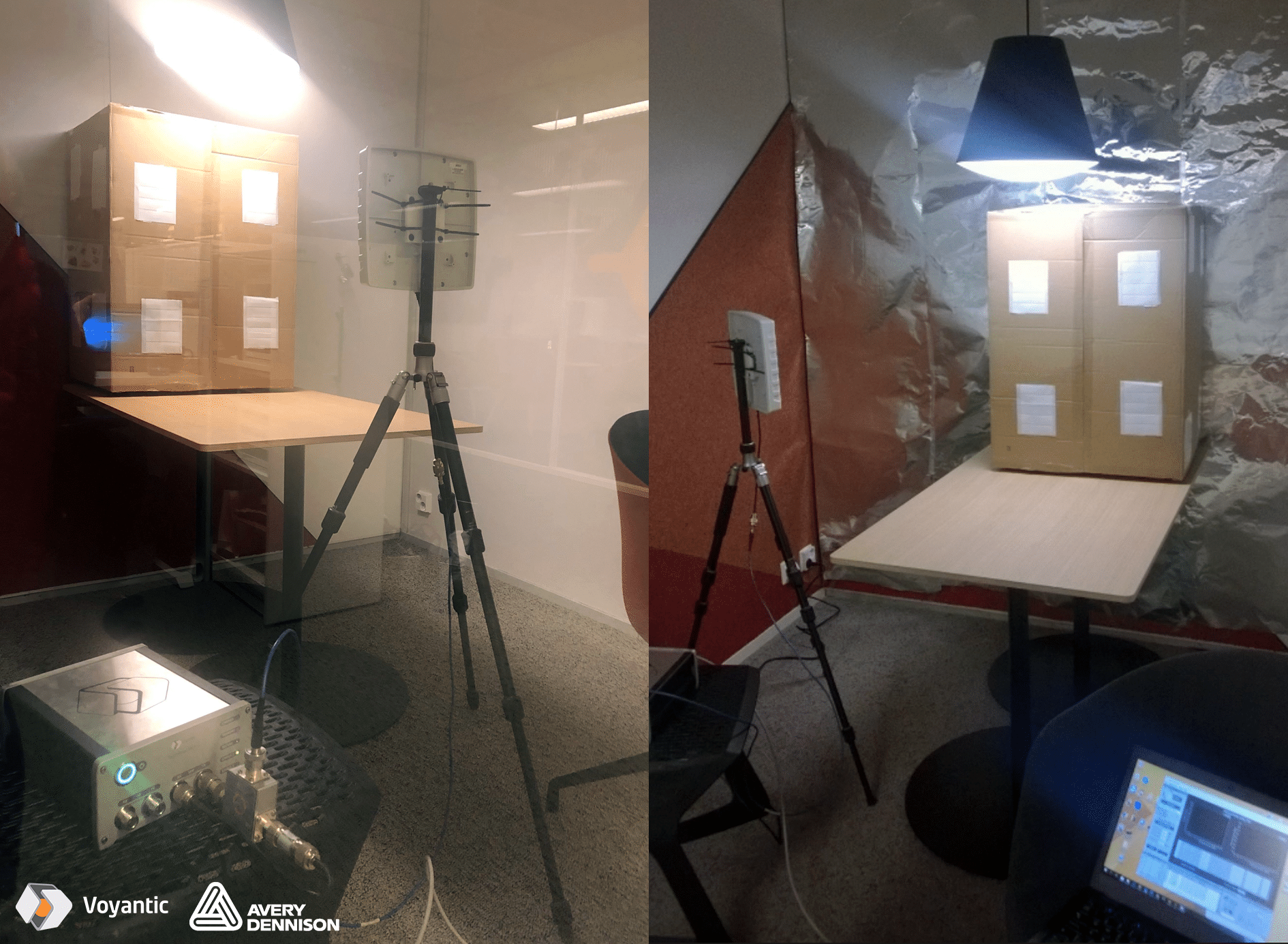
Around 2015, Stanley Black & Decker launched tool management solutions aimed at minimizing the effects of FOD (Foreign Object Damage) and ensuring the right tools are in the right places at the right time. This kind of tool management solution is quite attractive in industries like aerospace, transportation, healthcare, manufacturing, and construction. Though barcode is one of the most widely used methods of tools tracking in today’s market, RAIN technology has many advantages over the barcode. For instance, RAIN enabled tools can be read without a direct line of sight even when the tools are covered with dirt or grease. And multiple RAIN enabled tools can be read at once when they are inside a box or bag. RFID Detection Bag is a good use case.

More importantly, more and more tag suppliers are starting to provide RAIN tags for metallic product applications, like industrial tools or surgical tools. Confidex, Omni-ID, Murata, Xerafy, and Etagsys are examples. Some of them can offer customized RAIN tag for the market. This indicates that the RAIN tag industry is ready to serve the tool manufacturing industry.

Built-in RAIN RFID as Part of Product

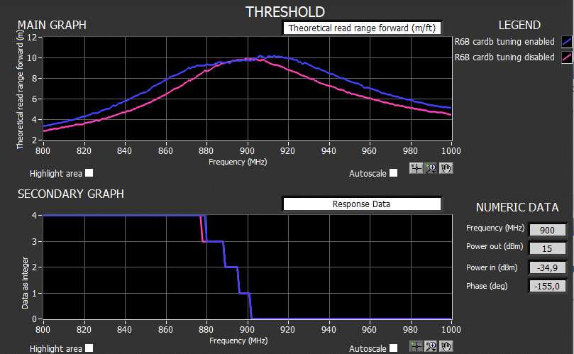
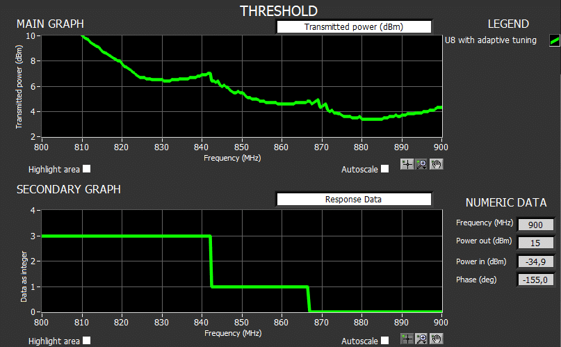
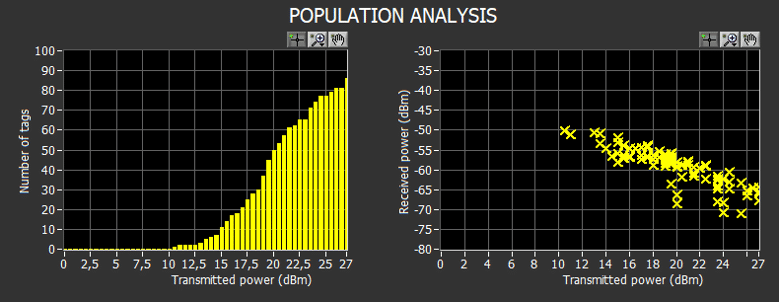
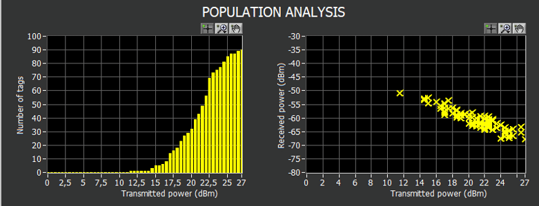
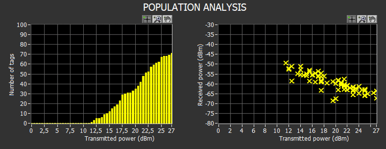
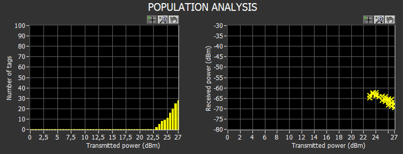
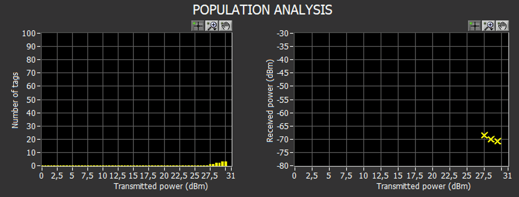
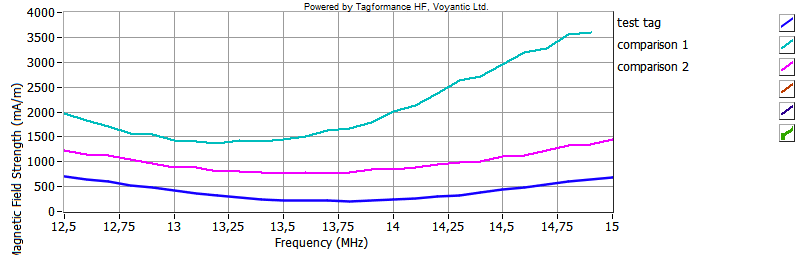
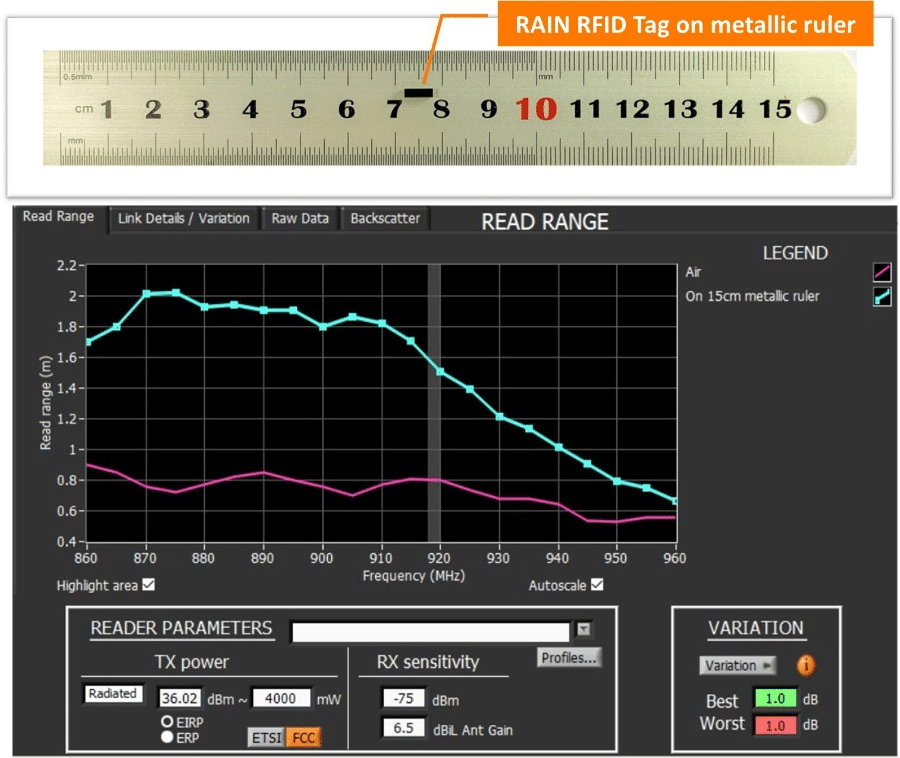
Using the tools’ metallic surface as an extension of the tag antenna to enhance RAIN RFID read range. A quite high percentage of tools are made of metallic materials, which normally play a negative impact on RAIN RFID performance. The below picture shows a RAIN RFID tag’s (6mmx2mmx2mm) read range when it is measured on air and attached on a metallic surface.

This tag is designed to cover Lower ETSI and FCC bands (865MHz – 930MHz). At the frequency around 920MHz, the tag read range is 0.8 meters when measured on air. If we put the same tag on a 15cm metallic ruler, just like the metallic surface of tools, the read range increases almost 100% to around 1.6 meters.

Tiny RAIN Tag measured on air and metallic surface, 4W EIRP with receiver sensitivity of -75dBm

An innovative tag antenna engineer should think about how to integrate the tag antenna into the tools and turn the challenges of metal into the advantages. Besides, instead of labeling or patching tags on tools after they were produced, embedding RAIN RFID tag into tools in design and production stages not only enables seamless tracking of each tool from the factory to the consumer, but it can also prevent people from removing RAIN tag easily.

Global Regulations

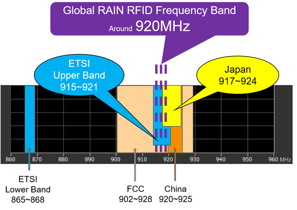
We know different countries have different regulations for RAIN RFID frequency bands. The good news is that Japan had migrated its RAIN RFID frequency band down to 917MHz – 924MHz in 2012. And the European Commission decided to add a new frequency band, Upper ETSI_915MHz – 921MHz, in 2018. By the time of writing this article, about 20 countries in Europe have adopted at least part of the Upper ETSI frequency band for RAIN RFID application. This means that sooner or later, we are going to have a global RAIN RFID frequency band which is allocated around 920MHz. What does it mean for the tool and RAIN RFID industries once the global frequency is widely adopted?

Global frequency simplifies the production of RAIN RFID enabled tools/items. The same RAIN RFID enabled tools can be used and sold worldwide. This will help to scale up production and reduce the cost.

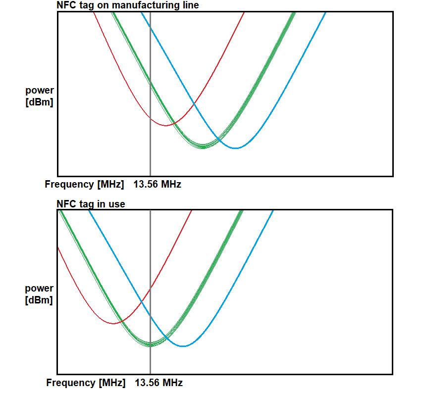
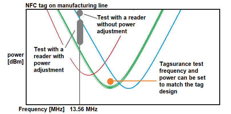
This opens the possibility to optimize tag performance for the narrow frequency band tag around 920MHz. Either tags can be made smaller, or longer read ranges can be achieved, read more from Voyantic CTO Dr. Jesse Tuominen’s blog. Though the variation in the RF performance has a larger impact on read ranges of a narrowband tag than on a broadband tag, fortunately, Voyantic’s Tagsurance UHF has proved to be a great solution in tackling this challenge.

Global standards’ frequency range

No doubt, RAIN RFID provides much superior performance and potential capability compared to the barcode. However, the initial investment of adopting RAIN RFID technology is still more expensive. And it is true that RAIN RFID is not going to replace the barcodes entirely. In some use cases, the combination of RAIN RFID and barcode can be the optimal solution. But I want to point out: after a decade of market development, technology advancement, the cost decrease of RAIN components plus the global regulation change, RAIN RFID is now a feasible solution for the tool industry.

Benefits of RAIN Enabled Tools Management

I recently visited some tool manufacturing companies in Taichung and asked them what are the major problems that the tool users are facing. Their answers include lost, stolen, and misplaced tools. To be honest, I am a little bit surprised by such answers, but it again explains the importance of tool management. RAIN RFID is the ideal solution to reduce the pain points and inefficiencies. From the tool user point of view, RAIN RFID together with other IoT technologies can enhance tool management, for example:

  • Locating and tracking tools become easier
  • Improve security and avoid internal/external thefts
  • Increase tools utilization and availability due to full visibility
  • Minimize the effects of FOD
  • Enhance automation of alerts and reports
  • Eliminate human error and increase management data accuracy
  • Reduce total cost of ownership of tools

The demand for better tool management is apparent, and the market is huge and worldwide. The traditional tool companies surely need to think about how to take this demand as an opportunity and reinvent themselves with RAIN RFID. From my view, tool companies can gain invaluable business advantages if they successfully embrace RAIN RFID into their businesses:

  • Differentiate the product from the competition. This is an especially good opportunity for small and medium-sized tool companies to transform themselves from purely manufacturing to IT-driven business.
  • Sell more higher-value products than tools, for example, smart carry cases, smart drawers, and tools management software.
  • Facilitate sales if the IT system is well designed and developed. Then the customer can check data from smartphone and place order, for instance:
    • Data shows XX2 and XX5 are used over 90% of the time, click here and order both.
    • Data shows XX4 has not been seen in a month, click here and order a new.
  • Every RAIN enabled tool has a unique identification number which can be utilized for anti-counterfeiting and supply chain management from manufacturing to customer.

I am sure there are many more benefits that RAIN RFID can contribute to the tools management applications. I will leave some room for the imagination of the readers. Now let me briefly describe how to implement the RAIN RFID tracking system. There are some possible ways to carry out:

  • Tool company makes the whole solution in-house, including the IT system development and tag antenna design.
  • Tool company outsources RAIN RFID part to several different professional suppliers who provide software development, tag antenna design, and other components independently.
  • Or tool company cooperates with an RFID solution provider to cover all RAIN RFID related tasks.
  • Software company develops and sells tool management solutions to end-users.

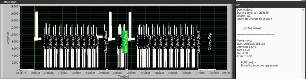
It does not matter how the tool management solution is built; the performance and the tuning of RAIN enabled tools need to be carefully tested. Otherwise, the readability would be a big issue. And it is necessary to remind new players that commercial UHF reader is unable to verify RAIN RFID performance. After all, the reader is designed for the application, not for tag design and production quality control. SAG’s story in Taichung Taiwan will explain why it is important to utilize the right testing equipment in the R&D and the production line.

GS1 TIPP

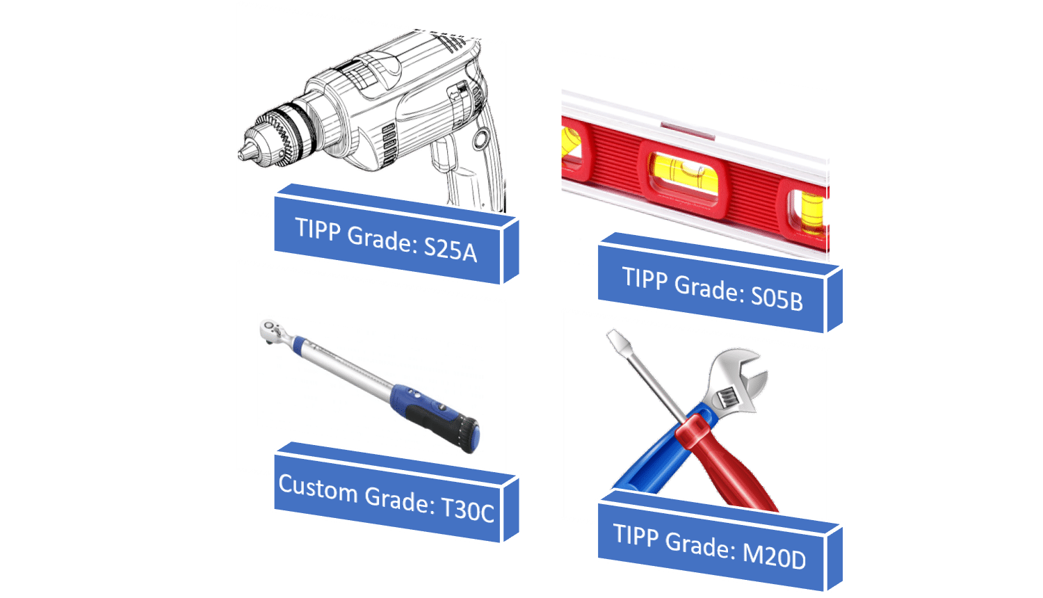
Once the performance of RAIN enabled tools is verified in the actual use case, the tool company can consider applying GS1 TIPP [Tagged-Item Performance Protocol] to streamline RAIN enabled tools specifications. GS1 TIPP is a RAIN RFID grading system developed initially for the supply chain management in retail, but it can be applied outside retail to scale up RAIN RFID applications across industries. Currently, there are fifteen TIPP grades, and tool company can select the grade(s), which can reflect the RAIN enabled tools’ minimal performance requirement. By doing this, it will simplify the communication among tool company, solution provider, and tag supplier. After all, grading is a much more efficient way to define the RAIN enabled tools’ performance. In case the existing grades do not meet the performance requirement, the tool company can submit a new performance grade to GS1 for validation or even create a custom grade.

TIPP Grades or Custom Grades can be used to verify RAIN enabled tools performance

In addition, the tool company can use the grade to source RAIN tag or RAIN enabled tools from several different suppliers if the specified grade level, tag size, and tagging method are met. GS1 TIPP also gives RAIN tag suppliers more flexibility in how they design the tag. This will encourage the tag supplier to be more innovative and creative to design the products to maximize the business benefit. Finally, any company can build its TIPP testing lab based on GS1 guidelines, and operating GS1 TIPP testing is easy and straightforward. This will help the whole tool industry to scale up the deployment of RAIN RFID technology.

Voyantic is the only company in the world specializing in performance testing systems for RAIN RFID and NFC tags from R&D to manufacturing. If you have any questions about managing the quality of RAIN enabled tools, feel free to contact us.

Adaptive Front-Ends Are Here to Stay

Jun 30, 2020

中文版 Chinese version

Impedance Matching

Matching the transponder antenna well to the chip impedance has always been the cornerstone of a well-performing UHF tag. For antenna designers, it is lightly frustrating that each chip brand and model seemed to have their unique impedances, therefore various versions of the same antenna are needed for different chips models.

On the other hand, from the chip designers’ point of view, it must have been frustrating that the tag antenna is never comfortably operating in free space, but always attached to various materials needing different tuning to operate optimally again.

For a long time, it has been known that impedance tuning does not need to be a permanent compromise, but can be actively re-tuned. This has been the norm in many wireless communications and roughly ten years ago this was introduced to UHF RFID as well. The first company to open the game was RFMicron with their ”Chameleon technology” in the Magnus® family of chips.

The early chips had a 5-bit tuning register, giving 32 different and successive tuning states, wherefrom the chip chose the optimal. Since the register value could be read back, the biggest value proved not to be the improved tuning, but the information of how much was tuned. This was turned into a clever way of performing RFID sensoring and later chip versions had an improved resolution of a 9-bit tuning register.

Today, several mainstream RFID chip providers utilize self-adapting front-ends for the small performance gain it provides. Most notable companies utilizing this are Impinj and NXP. Here we are going to see how this alters the tag performance and how to gain visibility into this.

Visibility Into Tuning

First, let’s take a look into the Monza® R6B chip. Examining the memory map in the datasheet, it clearly tells that there are three bits in the reserved memory where you can read the current suggested tuning state. In addition, there is a single bit, by which adaptive tuning can be disabled.

Part of the Monza® R6B datasheet

So, to set the feature on or off in Tagformance® for testing, the simplest way is to perform any write test with the correct write parameters. Reserved memory, Word pointer 4, and write the last bit high/low to deactivate/activate the tuning. The current state can be verified by reading the same memory.

Write parameters for turning the adaptive tuning off. The memory map of the Monza® R6B reserved memory showing the change (in red) where the disable bit was activated. Read parameters to point to the three tuning bits to read back the current tuning state.

Below is a threshold of the tag both with the tuning activated and disabled. With the adaptive tuning activated, the area of optimal performance is seen to increase by +/- 10MHz for this particular inlay design. To monitor the used tuning state, do the sweep with the READ command and the correct read settings for the chip. This gives the ability to select “response data” from the drop-down menu to see what data the chip responded with to the READ. In this case, you can see the tuning goes from 4 to 0 in the ~20MHz stretch from 880MHz to 900MHz.

Sweeping a tag using a READ command while monitoring the tuning state.

How About the UCODE®?

The UCODE® 8 family from NXP works in quite a similar manner. The tuning state can be read back from the memory by pointing to the correct location as stated in the datasheet. The deactivation of the feature needs more involvement. It seems a non-zero access password needs to be set for the tag, and then the setting bit needs to be “toggled” in the secured state using the proper WRITE command as the BLOCKWRITE will not do it. As the UCODE® has fewer tuning steps, you can sometimes spot from the tuning curve the points where the impedance was changed. It’s as if the curve consists of a few cut-n-pasted curves. Well, because it kind of is.

A close-up of a threshold sweep of a UCODE® 8 based label revealing the discrete tuning steps.

Conclusion

Automatically adaptive tag ICs are here to stay. It might be that the advantage they provide is a little slim at the moment, but if there is a performance gain to be had, why not take it? For the antenna designer and tag producer, it is valuable to be able to also switch the tuning off when needed, to easier judge the antenna itself, perhaps against a simulation.

Alternatively monitoring the read response data “stepping diagram” is a simple tool to see if the design is functioning as it should. Eager to chat more about tag design with us? Feel free to contact our RFID experts HERE.

A Major Upgrade for Aerospace RFID Testing

May 15, 2020

中文版 Chinese version

日本語版 Japanese version

During this COVID-19 pandemic, as most airplanes are stuck on the ground and several large airplane orders have been canceled, aerospace is probably not considered the hottest market for RAIN RFID. However, eventually, this situation will pass, and more airplanes will be built. When that happens, the aerospace industry will be more ready than ever to use RAIN RFID, due to recent standardization work.

Back in 2015, I wrote about the aerospace industry as the pioneers of RFID:

“The aerospace industry realized that they need standardization for flyable tags as early as 2006. That is when a group of experts in the field decided to develop a standard under SAE International. SAE AS5678, “Passive RFID Tags Intended for Aircraft Use”, was born … In addition to environmental testing, the standard also describes RF performance tests for the tags. The standard described a very professional and well repeatable measurement methodology. But even more interestingly, the standard divided tag performance into performance grades, somewhat similarly to what the GS1 TIPP standard would do for the retail industry in 2015.”

Fast forward to 2020, in February, SAE published the third version of the standard, AS5678B Passive RFID Tags Intended for Airborne Equipment Use. So, what’s new in the standard revision?

The changes are mostly related to how the performance grades are defined. In earlier versions of the standard, tags were graded based on their read range, determined from their sensitivity. And that makes perfect sense: In 2006, the sensitivity of RFID chips wasn’t that great, and read range was nearly always limited by power delivery to the tag. Nowadays, that is not always the case. As the sensitivity of tags has improved, in more and more cases the return link from the tag to the reader may limit read range. This is reflected in the new standard revision; in AS5678B, the grades are determined by both minimum read sensitivity and minimum backscatter.

To give an example, for a tag to be classified for Grade X, the sensitivity of the tag on a metal plate has to be better than -12 dBm, and its backscatter strength needs to be at least -23 dBm. That corresponds to an expected read range of 6 m. But that’s not all. Because airplanes are expected to cross borders, and radio regulations are different in different parts of the world, this performance is required throughout the global RAIN RFID range of 865 to 930 MHz.

There is one more new element in the standard. It is no longer sufficient for one individual tag to pass a grade – a statistical element is introduced. A total of 30 tags needs to be tested, and their performance variation must be below a level defined in the standard.

Overall, I am quite happy with the new standard revision. With the new backscatter criteria, it is well in line with the development of the industry. The backscatter is required to be quite strong which means that most readers are able to read tags that meet the criteria – and that is probably a good approach. In addition, the statistical test brings a hint of a quality aspect to the standard.

As a final thought, there is one thing that I find curious about AS5678. No one is openly advertising to offer test services according to this standard. Customers often contact me to ask for a service provider. Some tag makers are obviously either testing their tags themselves or having them tested somewhere. Probably most of them use an external lab for the environmental testing and do the RFID part with their own Tagformance system).

But wouldn’t it make sense to have a one-stop-shop for AS5678B testing?

If you think that a lab that you know should start offering these tests, please let us know. If they already have the environmental part, we would be happy to help with the RFID part.

Learn How to Test UHF RFID Tags in the Aerospace Industry

Download The Essential Guide for UHF Tag Testing in Aerospace

Triple Your NFC Label Production Capacity

Apr 17, 2020

中文版 Chinese version

In a recently published success story, Mr. Kevin Kuo, Technical Manager of a Taiwanese RAIN RFID and NFC tag manufacturer SAG discussed the improvements they have seen in production after taking the Voyantic Tagsurance HF system into use. He mentioned the improved capability to detect tags that are not working as specified, and also 200% increased production capacity. In this article, I explain more in detail some background features enabling the improvements.

“Tagsurance HF testing speed is much faster than normal commercial HF reader. The UPH has been increased over 200% after Tagsurance HF replaced the commercial reader in our converting line. Tagsurance HF can sort out those weak performance tags that a normal reader is unable to achieve. More importantly, Tagsurance can also record each tag minimum turn-on power, which is very useful information for our engineers to adjust the machine manufacturing parameters and to enhance the tag quality control.”, said Mr. Kevin Kuo, SAG Technical Manager. Let’s look at the two main improvements in detail.

200% increase in NFC label tag production capacity after installing Tagsurance HF

This amazing capacity increase was achieved entirely without adding new machinery. The capacity increase has its’ roots in the Tagsurance system. Tagsurance is an integrated real-time system, whereas typical NFC readers are combinations of a reader, computer, and reader software, or at least combinations of integrated reader + computer and software. These divided systems spend some time in moving data between the system parts. With Tagsurance, there is no time wasted on any overhead activities, and the data handling is optimized.


NFC communication standards are powerful and enable a large number of different use cases. The downside is that in typical use cases, the communication time is not minimized. There is a lot of communication flowing between the tag and reader, even in a simple read. The Tagsurance system is purpose-built for high-speed production quality testing. Some of the typical reader functionalities are left out, and focus is on a higher speed.

The difference is clearly visible when communication of Tagsurance HF and an NFC tag is compared to communication between an NFC reader (smartphone) and a tag. In the below picture, the communication is recorded with Voyantic Protocol Analyzer hardware and downconverter. The time Voyantic Tagsurance needs for checking the tag quality is a fraction of the time a typical reader needs when reading the NFC tag.

Recordings of the reader to tag communication between Tagsurance and an NFC tag; and a reader and a tag. Tagsurance HF needs a fraction of a time compared to a typical reader.

Replacing NFC reader with Tagsurace increases production capacity because Tagsurance HF:

  • is an optimized real-time device
  • does not need overhead time for moving data between system parts
  • is purpose-built for high-speed quality testing
  • uses NFC protocols efficiently for quality testing

-> 200% production capacity increase

Sort Out Tags With Weak Performance

Being a quality test device, the Tagsurance HF is capable of accurately sorting out good tags from non-performing ones. It is more interesting to look at why a regular NFC reader cannot do the sorting as well.

It starts with NFC tag performance. NFC tags are designed for different uses and are thus tuned differently, that is: the frequency where the tag needs the least amount of power is different. This frequency shifts to the 13.56 MHz HF RFID frequency only when the tag is in its typical use.

In the production line, the tag is not in its typical use environment, but the reader is still limited to operate on the 13.56 MHz. As a result, the reader only shows if the tag operates with 13.56 MHz in the manufacturing line. And how the tag works with a reader on the manufacturing line may be completely different from – let’s say someone is having the label glued behind a glass window or carrying a travel ticket inside a wallet.

In the below example, the tag with red tuning is out of specs, but in a production environment, it may even appear better than the good tags, even though in use, it requires a lot more power (does not work as well).


Tagsurance HF is not limited to the reader frequency. It uses the frequency that is relevant for determining the quality of each tag design.


Another limitation of a typical NFC reader is that they are not accurate and calibrated test devices. Many readers just have their own (high) power level designed to maximize tag reading probability; some readers may have a power setting but not calibrated. As a result, the readers cannot properly detect tags that are working out of specs.

Having exact performance information also enables production personnel to adjust the machine parameters based on real data, and to enhance the tag quality. Our expert team has seen many cases of the tremendous impact of the Tagsurance system in various production lines with ‘side effects’ being improved transparency to Quality Assurance and better communications with suppliers and customers. Tagsurance is truly a unique asset that can drive impressive results in the production environment.

Download the Tagsurance 3 Catalogue

Learn in detail how the Voyantic Tagsurance UHF and HF testers can improve the efficiency of your organization!

RAIN RFID Deployed in High-Speed Production Machines: Aspects of Cycle Time

Mar 16, 2020

中文版 Chinese version

As RAIN RFID matures both technologically and businesswise, tagging requires scalable and flexible processes. I recently heard James Goodland, RAIN RFID Solutions Manager at NXP stating: “Going forward, the RAIN-ability of an item will be more likely integral to product design, rather than just added on an item” This implies a steady flow of new players and end-users getting into our industry, and the RAIN technology vendors need to be ready to support and help them out.

Beginning with this, the first of blog series with NXP® Semiconductors, Voyantic will address technical issues that should be considered when adopting RAIN RFID in various manufacturing environments. We shall start by understanding how the cycle time greatly affects your options, even down to the selection of the tag IC.

Translating Line Speed Into Available Cycle Time

Accelerating into the new decade 2020 RAIN tagging still dominantly relies on inlays which are converted either into tickets or labels. Printing of variable data, and encoding of RAIN labels, is done in a process that runs tens of meters per minute. Taking a figure of 30 m/min as a challenging benchmark example, and assuming a label or ticket length of mere 3.2 cm (1.25 Inch), the processing speed translates into 16 labels/sec.

Turning the numbers around 1 Sec / 16 labels gives 62.5 ms/label. This is the available cycle time in which you need to move in, process, and move out the label. If your RAIN encoding sequence stays within this cycle time, your production capacity stays unaffected.

Singulating the Tag Without Wasting Time

Quite often in a manufacturing environment, you need to singulate a RAIN label among others in the proximity. You can either use the protocol to do it or rely on skilled engineering.

Going with the protocol, you would first perform an inventory followed by the encoding process for the label. Inventory requires time specifically if high Q-values are used. This increases timing overhead, which you barely have in high process speeds.

An RF engineer can have a label singulated with careful triggering, use of dedicated antennas and appropriate reader settings. As a result, singulation does not add timing overhead at all. The Voyantic solution supports both of these approaches. Specifically, in high process speed, we usually prefer to handle singulation based on the antennas.

Efficient Cycle Time Can Be Close To 100%

A label does not need to be in the optimal position in relation to the antenna all the time for a robust encoding system to successfully complete the job. Thus, the efficient cycle time can be fairly close to 100%. This means the reader won’t idle at all when the machine runs at the specified maximum speed.

However, if encoding fails at high line speeds, you rarely have the luxury to retry encoding. If you’re working with an encoding system that is not reliable or stable enough, but you want to protect the production yield, you may need to bring the cycle time down to < 50% simply to reserve the time for a second encoding try.

An alternative strategy is to have a second reader available to process the failed labels. Obviously, a second reader adds cost and complexity and increases the space needed in the machine.

I would say that your overall preferred strategy in a production environment is to utilize RAIN encoding systems that have high reliability and high stability.

A Few Alternative Commands to Write With

All the GS1 EPC Gen2 (aka ISO 18000-63 standards family) ICs need to support the WRITE-command. The protocol also includes an optional command BLOCKWRITE, which was specifically developed to speed up the encoding processes.

It is up to the design of the IC to either support the BLOCKWRITE or not. Also, beware that the number of words that can be written with one BLOCKWRITE-command varies. Let’s look at how the NXP UCODE® 8 performs:

a) WRITE
WRITE protocol control (PC) word, UID / EPC 96 bits and access password (nine words) + lock + read : 66.5 ms

b) BLOCKWRITE
BLOCKWRITE PC word (1 word at the time), UID / EPC 96 bits (3 blockwrites, 2 words at the time), and access password (1 blockwrite, 2 words) + lock + read : 49.4 ms

Only the latter case satisfies the example limit of 62.5ms and even leaves a comfortable margin to play with. With that said Blockwrite can be a lifesaver. At the same time, the example shows that specifying the encoding sequence using Blockwrite requires expertise.

RAIN Tag ICs Keep on Improving

The design teams of IC’s need to calmly work in a crossfire of conflicting requests: please deliver a tag IC design which boasts a fantastic feature set, is smaller than the previous model and complies with RED. “And yeah,” adds the marketing expert with colourful graphs, “kindly make the new IC also more sensitive than any other RAIN IC in the market. OK?”

“OK, no problem” responds the Engineering Director, takes a longer-than-average-sip of Dr. Pepper and starts orchestrating the design effort.

Eventually, the new IC lands at the Voyantic lab, where various issues will be verified and addressed:

RAIN RFID Tag ICs Benchmarked for Write Speed

One of the IC characteristics we look at is the time required to perform the WRITE or the BLOCKWRITE operation. You rarely find those numbers in datasheets, and even if you do, it’s really difficult to make sense out of them. Although meaningless for the majority of RAIN end-users, when one encodes labels at max speed, this timing parameter has to be known.

If you’re fascinated to learn more, please download the “RAIN Tag IC Encoding Speed Test Result Overview”. As we’re writing the UID / EPC, ACCESS password, locking the memory and verifying the UID / EPC, not all the IC’s are under the example target of 62,5ms.

Download Results

The write speed of ICs may be dependent on the protocol settings. For the purpose of this story, we have used the same settings for all the different ICs, and those are specified in the document.

Is That All?

There are plenty of fascinating details of how an encoding system is engineered to perfection, but if you’re either designing or operating a label processing machine, this is pretty much the story of encoding speed.

Read the next part in our blog series with NXP: Scaling Up with RAIN RFID Tags: The Path to a World Where Every Item Has Its Own Digital Identity

Optimizing Counting Reliability With Well-Designed Reader Zoning

Feb 21, 2020

中文版 Chinese version

At RFID&WIoT Tomorrow 2019, Erik van Noort from Avery Dennison stopped by a Voyantic booth. He introduced a recently launched ShieldSense™ RFID blocking material. The material is for reader zoning and aimed to help system integrators in building better RAIN RFID systems.

After sharing some ideas, we decided to write an article explaining the reader zoning and how to use Voyantic Tagformance to check not only if the zoning works, but how well the zoning works. In this piece, we introduce the ShieldSense™ material with the Tagformance test results.

What Is Reader Zoning?

Reader zoning is a common challenge when building RAIN RFID systems. You want to scan tags in one area, but don’t want to read tags from another area nearby. For example, at a loading dock, it is essential to know that the item passes a specific gate and goes to the correct truck, and not to the next truck a few feet away.

Reader Zoning challenges

  • An apparel store has stock at the backroom
  • Every item in stock should be represented at the shop floor
  • With RAIN RFID it is possible to count and identify every item at the backroom and the shop floor, with a few minutes scan – quick enough to be done several times a day
  • The system can then generate an alert if an item type is not represented on the shop floor
  • Having each item represented on the shop floor is critical. If an item is forgotten, it would never be sold during the season and would have to be either heavily discounted afterward as the last season item, or even wasted

Reader Zoning – Test Without ShieldSense™

Conventional methods for reader zoning are

  • selecting reader antennas with different reading angles
  • planning reader placement
  • adjusting reader power levels
  • using the RSSI filter to prevent stray reads
  • applying RF shielding material aka RF blocking material

For testing the zoning challenge, I designed a simple test environment in our office. In one of our meeting rooms (“Front Room”), I had 100 tags placed on all sides of a cardboard box. In the next room (“Back Room”), behind a wall, there were another 100 tags placed on a similar box.

Photo: Test setup: 100 tags on the box in the Front Room, and another 100 tags in Back Rroom

My goal was to find reader settings that would allow the inventory of the 100 tags in the Front Room without reading any tags from the Back Room. In the test, I used an antenna placed on different locations and orientations in the Front Room. I used the Tagformance population analysis as a test tool. A combination of several test positions would correspond with someone doing an inventory count with a handheld RFID reader.

Results Without RF Blocking Material

There was no antenna placement and orientation in the Front Room with which all of the tags in the Front Room could be read. In typical good positions, 85% – 95% of the tags were scanned. One apparent challenge was that the light wall between the Front Room and the Back Room did not block the RF signal. With antenna orientations that gave the best read results in the Front Room, a good number of tags from the Back Room were also found. In some antenna positions, more tags were found from the Back Room than from the Front Room.

Figure 1: antenna position 1, tags scanned from the Front Room with different power levels

Figure 2: antenna position 1, tags scanned from the Back Room with different power levels

No antenna placement would give a decent amount of readings from the Front Room without giving any readings from the Back Room

Figure 3: antenna position 11, tags scanned from the Front Room with different power levels

Figure 4: antenna position 11, tags scanned from the Back Room with different power levels

Even if 100% reading was not achieved from any single antenna position, a 100% read rate from the Front Room was achieved when two antenna positions were combined. In practice, a 100% read rate would be easy to achieve by a simple handheld reader sweep. But, the combination of two positions gave over 90% rate also from the Back Room.

No power level cut would enable efficient zoning. At any power level with which tags are found from the Front Room, some tags are also found from the Back Room.

There is no difference at backscatter signal strengths from tags in the Front Room and tags in the Back Room. RSSI filter would not be efficient for reader zoning in this scenario.

After the first tests, it was apparent that the task is hard. There was no reading angle where power adjustment or RSSI filter could separate the items. In the test scenario, antenna placement, adjusting reader power, RSSI filter, or any combination of those would not solve the zoning issue.

Reader Zoning – Test With ShieldSense™

For the delight of fellow Voyanticians, I wallpapered part of the Front Room with Avery Dennison’s ShieldSense™ material. After shaking of the numerous “do they make foil hats of that” comments, I did the second part of the testing. I again placed antenna to different positions and tried to find an antenna position where zoning would work. In this test, I also used the Voyantic High-Power kit to boost radiated power beyond normal power levels, up to 39 dB ERP radiated power (antenna in the test had about 8dB gain).

Photo: Test setup without and with temporarily mounted ShieldSense™ (and not the prettiest wallpapering
with test equipment)

Results With RF Blocking Material

The positive effect of ShieldSense™ was apparent immediately. In most antenna positions tags from Back Room were not found

It was also noticed that in the original test scenario, some tags were leaning against the wall, and after applying ShieldSense™, those tags were leaning against the metal surface, making the tags non-readable.

Figure 5: antenna position 1, tags scanned from the Front Room with different power levels, ShieldSense™ in use. Some tags leaning against the wall

Figure 6: antenna position 1, tags scanned from the Front Room with different power levels, ShieldSense™ in use. any tag 10cm from the wall

Figure 7: antenna position 1, tags scanned from Back Room with different power levels, ShieldSense™ in use

There were still read angles that gave some readings from the Back Room when the power level was high enough. Most likely, the read is from reflections, the Front Room was only partially shielded, and in some antenna orientations, the signals have some reflecting paths even if the direct paths are blocked.

Figure 8: antenna position 6, tags scanned from Back Room with different power levels, ShieldSense™ in use

When the power levels and backscatter signal strengths are analyzed, efficient zoning parameters can be found. Using 30dB radiated power and applying -65dBm RSSI filter with a handheld reader

  • would give 5dB safety margin before read rate would drop to below 100%
  • would give 5dB safety margin before tags in the Back Room would wake up
  • about 8dB margin in RSSI until reader would accept the response from Back Room

These safety margins are likely well sufficient for ensuring reliable system performance also in the long run.

I am also convinced that expanding the ShieldSense™ coverage a bit around the corner instead covering just one wall, and applying it permanently instead of the temporary mount I used, the safety margins would increase by some dBs

With ShieldSense™ it is easy to find reader power levels and RSSI filter values with which zoning works, and safety margins are good for getting reliable reads as well as for avoiding stray readings.

About ShieldSense™

About Tagformance

NFC-Powered Storytelling – A New Opportunity for Printing Companies

Oct 22, 2019

中文版 Chinese version

The Finns drink more coffee than anyone else in the world. If you read more, you’ll see what it has to do with NFC.

In the past year, I have given half a dozen presentations aimed to label printers and converters considering entry to smart label manufacturing. Just recently I introduced RAIN RFID to a group of printing professionals from Thailand and elsewhere in East Asia and South-East Asia in ASPT 2019 event in Bangkok. Many printing companies are thinking about how to replace declining ink-on-paper business, and smart labels are a good option.

NFC Based Marketing is a Good Way to Start in Smart Labels

A frequent question from print houses is simple: “What should we do, how do we get started with smart labels?” Embedded in this simple question are a number of other questions:

  • How should we invest and what we need to buy?
  • What should we tell to customers to convince them about RAIN RFID or NFC?
  • How should we train staff from sales to operations?
  • and more

After the ASPT Symposium, we visited Doi Chaang Coffee, a Thai coffee company. The company is an example of using packages to support their brand story. And what a story they had! The way they supported it with bio-plastic materials and package visuals was just perfect. In my mind, the story connected to the print houses’ question of how to get started. And one clear answer started to emerge.

Obviously, following the NFC marketing route to smart label manufacturing is only one of the options, but I believe it is a good one. The approach can be used by printing houses regardless of their business area, location or details of operations.

Doi Chaang Coffee – the Story

Good Story Makes a Great Foundation

The Doi Chaang story is an excellent example of how storytelling is used in brand building. Having a great story helps a lot and that is a big advantage for Doi Chaang. The storyline has its heroes and villains; there are ups and downs in the plot.

After learning the story, and connecting the brand with the names and faces of individuals the consumer connection is deeper. It is not just a cup of coffee, but it is a cup of coffee from Doi Chaang region, from Mr. Pikor Saedoo and his family to me. When a company can communicate such a personal story to its customers, the likelihood of buying again increases. It is a very efficient way to improve brand loyalty.

What About the NFC?

For Doi Chaang, creating the story itself is not a challenge, as it already exists as part of the brand. Currently, the users are directed to the story through images and slogans on packages and brochures. The challenge is to get the full story to as many customers as possible by finding the right channel.

NFC Delivers the Story

Every customer that visits or purchases the Doi Chaang coffee without learning the story can be perceived as a lost opportunity for both the customer and the company. And that has everything to do with NFC.

NFC-enabled labels have many advantages, starting from the simplicity of use when the only required step is to bring your smartphone to the NFC label. Another big advantage is the full control over the brand message – rules must be followed, but there are no third party format requirements, policies or procedures for advertising. Last but not least, it improves the experience for the customers, leaving them more loyal to the brand of coffee they are drinking. If done right, NFC labels can help to build customer knowledge and focus segmentation efforts to deliver relevant and targeted content. A brand could also choose to drive online sales simply by adding a “Tap and Buy” NFC tag on the item.

Placing “tap me” NFC tags to tables and counters at Doi Chaang shops is likely to get several persons to tap the tag and see what is the content. And the content could be a video of the Doi Chaang story. With NFC the lost opportunity is saved. For illustrating the possibility we produced few tags for our internal use at the office. And placed them next to the Doi Chaang coffee we served in our kitchen. And people took the opportunity to tap & learn more about the story.

So, What Should the Printing Companies Do?

We made the tags with the Reelsurance machine. And that brings up the last point. When a printing company starts smart label manufacturing three things should align:

  1. There must be a customer with a need for smart label,
  2. There must be production equipment for making that type of smart labels,
  3. And there must be skills and knowledge to produce those labels.

Any Company With a Brand Name is a Potential Customer

When all of the questions: to whom, what and how are open, answering them becomes extremely hard. There are a lot of standards around RAIN RFID and NFC, there are numerous technology choices, and anyone can really need almost anything; so how do you know where to start? In my opinion, starting with NFC labels encoding for marketing purposes is a good choice. I believe it is easy to find customers interested in enhancing their storytelling and marketing. That is “to whom”.

Learn the Basics

This choice limits the technology challenges. An easy way to start is to purchase blank NFC labels and start with personalization – printing, and encoding. The tags would be ISO14443A tags encoded with the NDEF URL message. Voyantic Reelsurance automates this, you only need to know the web address to encode and the system takes care of the technical details. The inlay must be chosen, and that is something Voyantic can help with in the beginning. We will ask a few simple questions and help you to write specifications you can use in purchasing the blank labels. There are more possibilities in NFC than using it as a gateway to a website URL. It gets easier to expand the knowledge when you have already made the first step.

Reelsurance Tests and Encodes NFC Labels

The investment decision is also easy. When the use case is as clear as this, Voyantic can offer the complete reel-to-reel machine with quality testing and encoding capability in a single delivery. And our support includes getting started in manufacturing. The machine is upgradeable, different NFC cases can be made with the same equipment, and expanding NFC to RAIN RFID is the next milestone to consider.

Do you have a question about implementing NFC or RAIN RFID? Contact us and we will be happy to discuss!

NFC Tapping – Smartphone Performance Comparison

Jul 17, 2019

中文版 Chinese version

I recently visited an NFC forum meeting where I listened to industry presentations and discussed with many NFC industry experts. User experience, user expectation, and physical level interoperability of various NFC devices came up frequently. This prompted me to finish this article, a draft version was written already a while ago. I tested a few smartphones for NFC tapping user-friendliness and dug a bit deeper into the factors affecting the user experience.

Three NFC Application Types

When I think of NFC, I think of three very different application types and different experiences with them.

  1. Smart card: Think of a hotel keycard or a metro ticket. In my experience, NFC works smoothly and reliably in these applications. I have frequently had issues with magnetic stripe key cards, but NFC has worked perfectly. In these applications, a consumer carries the tag and a dedicated reader is used.
  2. Device-to-device: There are also emerging examples with excellent feedback of applications where 2 devices share information. For example, a phone placed to a center console of a car controls the settings of the car’s infotainment system.
  3. Simply tap: Third big promise of NFC is in applications where consumer carries a smartphone and interacts with NFC tagged items to receive more information. That is when the user experience changes – and not in a good direction.

The third application type – Simply tap – is the focus of this article.

Simply Tap Experience – Not So Simple

Promise: NFC works like waving a magic wand – simply tap.

It is a familiar situation: There is a web-link encoded to an NFC tag and the smartphone’s NFC is turned on. Enthusiastic user calmly extends the elbow and taps the tag with the top end of the phone – a move similar to a sorcerer waving a magic wand – but this time magic doesn’t happen.

Reality: Despite relentless tag rubbing with a smartphone – nothing happens.

Next try – slowly position the back cover of the phone on top of the tag – still nothing. Move the phone sideways on top of the tag; up to down; down to up; corner to corner – waving the magic wand did not work, maybe the NFC genie can be rubbed out from the tag. No. Check the settings. Try again. Ask a friend: “did you read it?” It should work – but it didn’t – no error message – nothing. A too common NFC user experience turns from a hopeful magic wand tapping into rubbing the NFC genie’s lamp into disappointment. What really happens? And what could be done for improving the user experience?

Digging Deeper: usually, NFC works, but details of the reading experience just don’t match the user’s expectations. In order to learn more, I looked more into what happens with smartphones and NFC. Here is what I found out.

Smartphone Reading Interval

Even if NFC is enabled, a phone is not reading NFC continuously. Instead, it checks occasionally if there is an NFC tag nearby waiting to be read. How often it is checked: As far as I know, there are no rules – most likely the interval depends on a lot of things: manufacturer’s preferences, operating system, power settings, other background applications taking up processor time, and many more. I tested two phones with Voyantic Protocol Analyzer. I found out that there is a big difference in how often phones try to read NFC tags.

Table 1. NFC Tapping With Phone Comparison – User Experience

Smartphone Reading Area

Different smartphones have different NFC reading areas. Reasons are not visible, but it is easy to come up with some ideas:

  • Different antenna positioning
  • Different antenna size and quality
  • Effect of nearby components
  • Different power levels

All in all, pointing a phone to an NFC tag is done differently from model to model.

Using phones’ default settings, I tested two phones.

  • With phone model A:
    the ideal position was pointing upper part of the phone in 30-degree angle towards the tag
  • With phone model B:
    the ideal position was slightly below the top part of the phone

Table 2. NFC Tapping With Phone Comparison – Positioning

Some phone models inform the user about the antenna position on the NFC setting screen, or in the startup screen. But some leave the antenna position hidden, only to be discovered by the user by relentless rubbing and experimenting.

NFC Tag Placement

In the first tests, the NFC tag was completely visible for the user, and it was possible to touch the tag. This is not always the case. In the second test I used Voyantic Reference Material Set to simulate “tap the window” use case. The inlay was behind a business card, which was behind a sheet of glass. The user experience changed completely – and not in a good direction.

A small change in tag placement can have a huge effect

Few millimeters between the phone and the inlay – slight detuning from the glass and the fact that exact inlay position was not known made things difficult. Some tags conveniently readable on air were not readable on “tap the window” application, and with most tags, exact phone positioning was needed.

Table 3. NFC Tapping With Phone Comparison – Through Glass

NFC Tag Sensitivity and Tuning

The above tests were made using an NFC inlay with 35 mm diameter round antenna – something that could be conveniently used in a price tag in a retail store. But tags are not equal. The inlay I used required 225 mA/m magnetic field strength for activation. When I tested two other “price tag size” NFC inlays with Voyantic Tagformance Pro the required activation energies were 750 mA/m and 1500 mA/m. Sensitivity and quality of the tag have an effect on the user experience.

Chart 1. Tag Sensitivity

When activation power increases, the practical effect is that a range of positions on which a tag can be read decreases. With both of the tested phones even weaker tags worked well when the reading position was optimal and touching the tag was possible. But slightly “mis-tapping” the tag left it unread and testing the “tap the window” use-case with phone model A was unsuccessful.

Too commonly NFC tag performance and quality are not really tested and suitability to an application is not properly evaluated. Often only antenna is tested with passive testing made with network analyzer – result tells about the antenna tuning, but that is not the full view to the NFC tag. When the chip is attached to the antenna, and when the tag is attached to an item, the tuning changes. And passive testing does not really tell anything about the required activation energy, which is the key. Only active testing tells the entire story. Below graph shows one NFC tag individual tested in 4 scenarios. Tag attached to a glass, tag on air, and antenna only.

Chart 2. Active and Passive Tests

Smartphone Functionality

The test was made with two phone models, one equipped with an Android operating system and another with Windows. Both of these try reading NFC tag periodically when the NFC is turned on, without any additional applications. The full list of NFC-enabled phones is available here.

iPhone and IOS were not tested since iPhone only allows reading NFC tag with a separate application – without it no amount magic wand-waving or rubbing the NFC genie works. An upcoming iOS 13 is supposed to change this.

How Could NFC Systems Be Improved?

What can the user do?
There is not much a user can do, the only reasonable thing is to “know ones phone”: How long it takes to read a tag and what is the best reading position. The best way to find these out is to take a working tag and try. No rubbing – just touch the tag with phones top few seconds using different positions and angles. In reality, the responsibility to improve user experience lies almost entirely on technology providers.

What can system integrators do?
System integrators control several items of the system: Which tag is used, how the tag is placed, how the tag is presented and so on.

  • User expectations should be steered to match the actual technology performance. Maybe replacing “tap me” with another phrase such as “tap to download” would steer the user to a longer action than a quick tap.
  • When personalizing the tags the “tap me” text should indicate accurately the NFC inlay position. Incorrect or inaccurate positioning decreases the usability and results in bad user experience.
  • Selecting the correct tag for an application is the cornerstone of a well-functioning NFC system. Applications and items vary – Sometimes it is possible to touch the tag with below 1 mm distance – sometimes the applications may require few millimeters reading distance. Tag tuning may also be affected by different materials on which the tag is attached. If a wrong tag is used, the system works poorly or not at all.

What can smartphone manufacturers do?
Smartphone manufacturers control the main interface between the NFC system and the user. If the interface works reliably and the use matched expectations, the system is likely to work well.

  • NFC reading should be enabled on smartphones without a separate application
  • Reading interval should be short enough to enable the smooth user experience
  • The phone’s antenna quality and positioning should allow intuitive “tap and read” in different scenarios: tag on table and tag on the wall.
  • It would help system integrators and tag manufacturers to know the phone profiles – how strong the magnetic field the phone’s NFC reader can generate at different distances. This data could be compared with the required activation energies in different applications.

What can NFC tag manufacturers do?
NFC tag is the second technical item in an NFC system. Well performing good quality NFC tags are obviously the tag manufacturers’ responsibility.

  • Tag manufacturers should ensure that tag sensitivity is sufficient and quality matches the application and expected user experience. Materials between phone and tag should be taken into account.
  • When printing the tag the “tap me” or other guiding text should be correctly placed and guide user expectations to the right direction.

What should NFC forum do?
NFC Forum is known for creating and maintaining the NFC standards and advocating NFC use among other industries and to consumers. In my opinion, this is also a source for some of the user experience issues.

  • In addition (or even instead) of standardizing the NFC tag performance with technical terms such as defining activation magnetic field, NFC Forum could standardize (or at least recommend) user experience criteria. A tag may have one activation energy but the user experience changes, if the tag is placed on cardboard, versus behind a window. User experience should be similar in both cases. Complexity increases further if the same performance criteria is forced to device to device and smart card applications. In my opinion, the user experience requirements should be different for the three application types
  • NFC forum should recommend system integrators and manufacturers to indicate clearly where the tag is placed, and where the phone´s antenna is. Discussion on this topic are on-going among NFC Forum members, and I have seen excellent practical ideas.

I am eagerly looking forward to the bright future of simply tap NFC.

Do you have any thoughts or questions about the NFC tapping? Contact us – I would be happy to discuss this in more detail!

Radio Equipment Directive Safeguards RAIN RFID Users and Vendors

Jun 24, 2019

中文版 Chinese version

RED Puts Accountability to RAIN RFID Component Vendors

RED is the Radio Equipment Directive 2014/53/EU and it applies to all radio equipment that’s used in Europe. This directive was passed already in 2014 but at first there was a bit of uncertainty of how it exactly works concerning RAIN RFID. Then the ETSI EN 302 208 standard was updated to v.3.1.1. in 2016, which already addresses both the lower and upper ETSI bands – well done Brussels! That standard document put clarity into how RED is enforced concerning RAIN, and that RAIN component vendors are accountable.

RED Looks After the Interests of RAIN Vendors and End-users

At first thought one could arrive at a hasty assessment: RED is nonsense – nothing more than a cost-of-doing-business with very little reward for anyone besides testing service providers. Moreover, it adds to the cost of technology for end users and slows down the go-to-market process. Who reads 45 pages of standard text these days anyhow…

I see RED in a different light: the directive aims at utilizing the limited frequency spectrum that we have at maximum benefit to those utilizing the spectrum according to regulations. This means various radio systems can co-exist, can be relied on, and don’t put the health of users at risk. And looking at the most relevant document ETSI EN 302 208, there is actually 69 pages most of which you can discard.

RED requirements for RAIN RFID systems operating at lower and upper ETSI frequency band

RAIN Tags to be Tested in Their Typical Environment

For RAIN RFID vendors it’s important to understand RED testing is necessary for RAIN components, including tags and all types of readers. As I focus on tags specifically, the different nature of a RAIN tag and a RAIN tagged item needs to be considered. This is an aspect where the directive requires interpretation. Chapter 4.1 “Environmental profile” states that “The technical requirements of the present document apply under the environmental profile for the operation of the equipment, which shall be declared by the supplier”.

My practical interpretation is, that if someone is providing a windshield tag, it should be tested while attached to a windshield. At the same time, it’s not necessary to test the windshield tag on all the windshields in the market.

Direction of Maximum Gain is Interesting

Under “Tag Conformance Requirements” the clause 4.5.1.2 “Definition” states that

The effective radiated power of a tag is the power radiated by its antenna in its direction of maximum gain under specified conditions of measurement.

For the example of a windshield tag, the direction of maximum gain probably raises no debate.
However, as you take an on-metal tag with a resonating antenna structure and attach it on a couple of randomly selected metallic objects, you will arrive at various orientation patterns. It’s, therefore, necessary for a vendor really to consider what a “typical environment” is for a specific RAIN tag type.

All Common Types of Smart Labels Need to be Tested

Back at the RFID Tomorrow event in Darmstadt 2018, I gave a presentation with a reference to RED and RAIN tags. The picture below shows what test aspects of RAIN tags RED specifically looks at.

Followed by that I presented a slide “Reason for Concern”. In October 2018 I thought that generic smart labels would easily pass RED tests. With the new experience gathered I today need to slightly revise my message: it’s very necessary to test and make sure the backscatter signal strength stays within the limits!

How to Test for Compliance With RED?

Our superhero engineers have implemented RED tag test capabilities into the Voyantic Tagformance system. A white paper describes how tests can be conducted at different levels of accuracy. As quite many in the RAIN industry have access to a Tagformance, a system upgrade with an ETSI RED test kit brings the necessary testing capability quickly available.

Download Whitepaper

The tests themselves are straightforward and even relatively quick to implement. Also, the results evaluation is made easy. The whole procedure is illustrated in a tutorial video:

Do You Have an Alternative to Following RED?

In fact, you do, because following a harmonized standard is voluntary. This path is addressed in FAQs for RED, but to paint the essence in a nutshell: Those who choose not to comply with the RED follow a conformity assessment procedure where they demonstrate to a notified body that the product complies with all the necessary requirements. The manufacturer assumes full responsibility and liability.

That’s the story today. If you have any questions or comments, please contact us.

Using TIPP Tagged Item Performance Protocol Outside Retail

May 02, 2019

中文版 Chinese version

GS1 RAIN RFID Performance Standard Helps to Scale up RFID Across Industries

RAIN RFID is being adopted increasingly in several industries such as automotive manufacturing, healthcare, and pharma. Because of the growing number of implementations, there is an increasing need for a solution that helps to scale up the implementations.

One of the bottlenecks seems to be specifying RAIN tag performance in a way that enables the use of tags from several manufacturers in a system. Need for performance specification or for a method to classify tags comes up more and more frequently in industry meetings. The good news is that pioneering industries have solved these questions earlier, and there are working solutions ready for adoption.

Why Performance Specification is a Thing?

Most RAIN RFID system deployments cover a single use case, utilizing one type of tags in one way. When users become familiar with the system and learn about the possibilities, the deployment starts expanding:

  • New types of readers are added
  • New types of items are tagged
  • New use cases are added.

End users naturally expect that all the components have solid readability across the entire deployment. At the same time scaling up typically creates a need to use several tagging suppliers. This ultimately creates the need to specify performance instead of purchasing a tag model.

Keyword is “Scalability”

GS1 TIPP is a Ready Solution

GS1 Tagged Item Performance Protocol (TIPP) was originally developed for retail use. The methodology is universal and works perfectly for any RAIN user industry such as pharma, healthcare or automotive. The performance classes aka grades and methodology are already used in several applications beyond retail. Adopting GS1 TIPP is easy when a working tag and tagging method has been found:

  1. The item or group of items can be tested in minutes for finding out which performance classes it fulfills.
  2. The test outcome is the performance specification.
  3. In addition, tagging instructions and quality requirements are created easily.

For example:

Tagging instructions: Item X is tagged by placing the tag on the top part, as shown in the photo above
Performance specification: Tagged item performance should meet TIPP grade S30B
Quality specification: Inlay quality variation should be within +/- 2dB
Encoding specification: The tag should be encoded with 96bit SGTIN code and permalocked.

Scale up by leveraging existing standards

There are several benefits for adopting GS1 TIPP standard:

  • Dozens of tag manufacturers have the TIPP test capability in-house.
    The specifications would be quick to roll out.
  • There are several third-party test centers offering testing-as-a-service in several continents.
    Anyone has access to the testing.
  • The standard already includes several performance grades – with high probability one of these performance classes can be used in any application in any industry.
  • There is a self-improving methodology included. If there are no suitable grades for a new industry or application, a new grade can be added and it is automatically distributed to tag manufacturers globally.

Re-inventing the Wheel Creates New Problems

Developing new, parallel methods brings problems: new investments would be needed, and communicating new requirements with new ways to dozens of tag manufacturers globally is risky and slow. All in all, the adoption would be slow and instead of helping to scale up the industry a new bottleneck may emerge. It took industry experts more than four years to develop the GS1 TIPP into a global standard, which only shows how extremely slow it is to create a new standard.

In my opinion, the best way to scale up is to leverage the existing EPC standards, and GS1 TIPP is one of the standards in the EPC standards family.

Do you have any thoughts or questions about the GS1 TIPP methodology? Contact us – I would be happy to discuss this in more detail!