Emerging Technologies and Expanding Applications – A Look into RFID Research in 2023
Jun 26, 2024
RFID research in 2023 shows how fast the technology is evolving beyond its traditional use cases. Recent studies explore new application areas, improved tag and antenna designs, smarter sensing capabilities, and advances that push performance, reliability, and sustainability further than before. From logistics and retail to healthcare, smart materials, and emerging IoT use cases, academic research continues to play a key role in shaping what RFID systems can do next. This article takes a closer look at the most interesting RFID research topics of the year and what they signal for the future development of RFID technology.
The following analysis examined the headlines of RFID research articles published in 2023 in Google Scholar. There has, undoubtedly, been an impressive selection of fascinating research topics, which means I can’t include all topics and papers in this analysis even if I wanted to. But let’s look at some of the most exciting topics and trends of 2023.
Application-oriented research seems to be on the rise, which is understandable given the industry’s growing and maturing. RAIN RFID use is expanding rapidly to include volume use cases outside of retail, such as healthcare, logistics, manufacturing, and many other fields. Application research supports this market development.
Research expanding from technology development to technology use is a positive sign. The spread of types of applications tells about the applicability of RAIN RFID in several areas.
RFID Sensing in Healthcare
Integrating RFID technology, sensors, and medical diagnostics advances biomedical sciences to a whole new level. This is an interesting and growingly versatile RFID research area.
- A paper titled “Semi-Implantable Antenna Integrated into a Medical Needle” presents a method to equip a polymeric cannula with a battery-less RFID IC and temperature sensor for remote monitoring of catheter sites.
- This paper introduces a miniaturized, battery-less RFID sensor capable of measuring temperature and humidity within pharmaceutical packaging: Miniaturised and Battery-Free Temperature and Humidity Sensor for Smart Pharmaceutical Packaging
- Exploring the correlation between drug formulation and radio frequency performance in RFID-enabled pharmaceutical products investigates the impact of various liquid drug formulations on the performance of pre-optimized UHF RFID tags.
- This paper proposes a wireless transcranial link using capacitive coupling in the RFID-UHF band for noninvasive monitoring of brain biophysics: Capacitive Coupling for RFID-based Wireless Transcranial Link for Patient-Centric Medicine
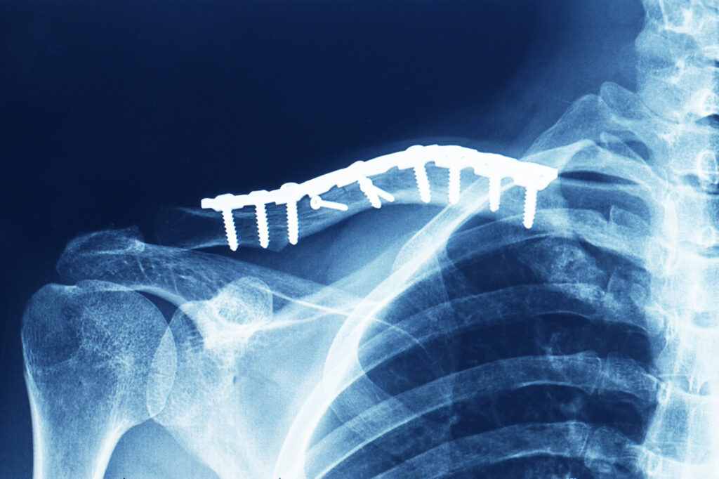
- The following study, “Augmented Implanted Orthopedic Fixators with an Embedded Temperature Sensor for Early Detection of Deep Infections” transforms an orthopedic fixator into a data generator using passive UHF RFID technology.
- This paper presents a passive UHF RFID-enabled implant to detect early signs of loosening in knee prostheses: Implant-Based UHF RFID-Enabled Sensor to Detect Loosening of Knee Prosthesis
- This article proposes a battery-less RFID sensor-based Thermal Monitoring Sheet (R-TMS) for hyperthermia treatment: Epidermal RFID-Based Thermal Monitoring Sheet (R-TMS) for Microwave Hyperthermia
- The paper “Continuous Detection of Fluid Leaks Into the Body by Means of Partially Dissolvable Antennas” proposes a wireless monitoring system for detecting internal fluid leaks using an implanted UHF RFID antenna.
On-metal Tag Design
Following the trends of previous years, several papers have been published on developing tags specifically for tagging metallic objects.
- This paper, “Small On-Metal Passive UHF RFID Transponders With Long Read Ranges” introduces two compact wide-band passive UHF RFID tags for on-metal applications.
- A Hybrid Meandered Line-Slot Patch Antenna for On- and In-Metal RFID Tag Design: A novel hybrid patch antenna featuring a meandered line and complementary slot for enhanced broadside radiation is proposed for RFID applications.
- This paper proposes a compact, flexible UHF RFID tag for metal surfaces featuring a resonant ring and surface-etched slots: Bendable Folded-Patch Antenna With Resonant Ring Manufactured Based on Foam Support and PET Substrate for On-Metal UHF RFID
- In the following study, a polarization-insensitive planar patch antenna with embedded serial capacitance is proposed for metal-mountable RFID tags: Polarization-insensitive planar patch antenna with large embedded serial capacitance for on-metal tag design
- This paper presents a compact, flexible UHF RFID tag antenna designed with two concentric step-impedance rings for metal-mountable applications: On-metal UHF Tag Antenna Design Using Concentric Step-Impedance Rings
- The paper “Planar Inverted Antenna With Embedded Patch Excitor for On-Metal Tag Design” introduces a low-profile, metal-mountable tag antenna design that embeds a non-resonating patch within a planar inverted antenna structure.
- This paper proposes a novel low-profile top-loaded monopole antenna for on-metal omnidirectional RFID tags: A Low-Profile Top-Loaded Monopole Antenna for On-Metal RFID Tag Design
- The following paper introduces four compact single-layered planar antennas for flexible UHF RFID tags designed for various on-metal applications: Design and optimisation of single-layered on-metal tag antennas for ultra-high-frequency radio frequency identification
Passive RFID sensors
Batterylessness is highly popular when it comes to passive RFID sensors.
- A Battery-less NFC Sensor Transponder for Cattle Health Monitoring introduces a battery-less NFC sensor transponder for measuring biomarkers in cattle tear fluid.
- This paper presents a battery-less NFC sensor for museum artefact monitoring: Performance Characterization of a Battery-less NFC Sensor for Museum Artifact Monitoring
- Battery-Free NFC Sub-ppm Gas Sensor for Distributed Gas Monitoring Applications at Room Temperature proposes a low-cost, battery-less NFC tag for gas sensing using a resistive gas sensor.

Coupling Effects
The following studies indicate that understanding and optimizing coupling effects are crucial for enhancing RFID tag performance in various applications.
- This paper proposes a statistical analysis of RFID system performance in high-density contexts: Statistical Evaluation of the Coupling Effects Between Tags in a UHF RFID Forward Link
- UHF RFID tags on paper based on capacitive coupling between bare die IC and antenna demonstrates attaching an RFID bare die IC to a paper-based antenna using a non-conductive adhesive
- This study designs, investigates, and compares various coupling circuits for textronic RFID transponders: The Influence of the Design of Antenna and Chip Coupling Circuits on the Performance of Textronic RFID UHF Transponders
RFID Applications
Papers examining RFID applications are, not surprisingly, a rising research area.
- The following RFID research examines the operational behaviors of an armored truck company (ATC) and its interactions with banks, retailers, and ATMs: Traceability of Financial Assets Through the Application of the Internet of Things
- The work “IoT-enabled vehicle recognition system using inkjet-printed windshield tag and 5G cloud network” develops and tests an IoT-enabled vehicle recognition system.
- This work develops and tests an IoT-enabled system for detecting vacant parking slots using low-cost, inkjet-printed passive UHF RFID tags: IoT-Enabled Vacant Parking Slot Detection System Using Inkjet-Printed RFID Tags
- The following paper, “An RFID Tag Movement Trajectory Tracking Method Based on Multiple RF Characteristics for Electronic Vehicle Identification ITS Applications” proposes an RFID tag motion trajectory tracking method using multiple RF features for intelligent transportation systems.
- This study reports a sustainable method for preparing highly conductive screen-printing graphene ink by recycling cellulose solvents: A sustainable approach towards printed graphene ink for wireless RFID sensing applications
Conclusions
In conclusion, the RFID research published in 2023 demonstrates significant advancements in various fields, including healthcare, pharmaceuticals, and intelligent transportation systems. These studies highlight the expanding applications of RFID technology, from improving medical diagnostics and monitoring to enhancing the efficiency of industrial processes and urban infrastructure. The ongoing innovation and diversification in RFID applications underscore the technology’s growing impact and potential for future developments.