Trigger Sensors in RFID Production – Get It Right
Sep 06, 2023
In the past couple of years, I have been following several projects where the Voyantic Tagsurance systems have been integrated into production machines. Surprisingly often, the biggest problems have been related to triggering – “seeing” accurately when a label enters the system. The experience even turned into a rule of thumb: “If something does not work correctly, first check the triggering”. I have realized that getting the triggering to work correctly is of utmost importance.
At the same time, I have been pleased to see plenty of new Tagsurance features that help to avoid challenges with triggering.
In this article, I will discuss:
- Why it is so critical to get triggering to work perfectly?
- Why triggering can be difficult?
- How do Tagsurance 3 features help get the triggering reliable?
Principle of Triggering
All (or most?) trigger sensors work with the same few simple principles:
- Each sensor has a physical parameter it monitors. Depending on the sensor type the parameter can be the strength of light of a certain color (through a beam sensor), amount of conductive material (an inductive sensor), darkness of view (a contrast sensor), darkness and shade of color in view (a color contrast sensor), and so on.
- The sensor has a window of view. It only senses the parameter within this window of view.
- The sensor is trained/programmed to recognize when the parameter passes a threshold value. For example, if a view of a contrast sensor gradually turns from white to light grey to darker greys and black in the end, the sensor is trained to see a specific point in the continuum as the threshold point.
- At the threshold point the trigger sensor’s digital output changes from 1 to 0 (or vice versa, or the trigger sends a pulse).
Why does triggering need to be perfect?
Any problem in triggering will affect the overall quality system performance, production machine performance, and production process accuracy and efficiency. Some triggering problems are obvious, some are more subtle.
- Missed triggers
- Double triggers
- Not detecting missing labels
- Suboptimal timing
- Suboptimal positioning
If a trigger is missed on a tag, that tag flies through the machine undetected. It would not be tested or otherwise processed. It would not be recorded in production logs. It would not be counted to output quantity. But it would be on the roll and get delivered to the customer – free of charge, of unknown quality, and probably incorrectly processed. With a high likelihood, there would be problems awaiting the customer.
A double trigger is an opposite issue. One label is counted twice and attempted to be tested and processed twice. There is a high likelihood that one or both of the process actions fail. The customer would only receive one label instead of the two that were counted. Counts, log files, yield data, and so on would be incorrect.
In some processes, a label can be detached from the liner. Recognizing these missing labels can be important for keeping the entire process optimal. The challenge is to notice when a label does not pass the trigger sensor when expected. A bit of smartness needs to be added to the trigger signals.
In RFID label production machines, there are usually only a few milliseconds to test an individual tag. Accurate results are based on the inlay being at the right position on top of the test coupling element when the test is made.

Why triggering can be difficult?
The root causes for triggering difficulties vary:
- One sensor type may not fit each produced material.
- The “edge” may not be clear enough for the sensor in use.
- There may be multiple edges per inlay at the path crossing the window of view.
- When the liner moves, it may also drift across the lane, or vibrate up and down.
- Materials have imperfections.
- With fast-moving material, it is not easy to see the exact position of triggering – optimization is difficult.
In RFID label machines typical materials to trigger are:
- Inlays
- Cut labels
- Uncut labels
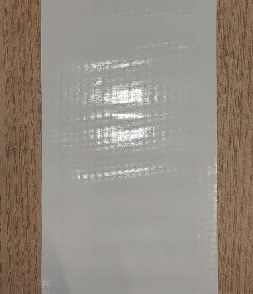
Cut labels are usually the easiest material with clear edges between the label and out of the label. Triggering issues may arise, for example, if lighting conditions change. Glossy materials would amplify the difficulty. The issue is that the threshold position within the window of view can drift if the sensor receives a variable amount of light. If the color of the liner is close to the color of the label, detecting the edge may not work with a contrast sensor.
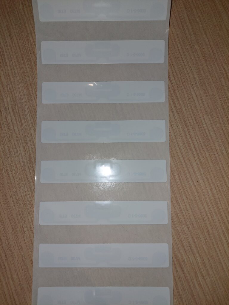
Uncut labels without a trigger mark cannot be triggered with contrast sensors. Depending on the material a through-beam sensor or metal sensing inductive or capacitive sensor is needed.
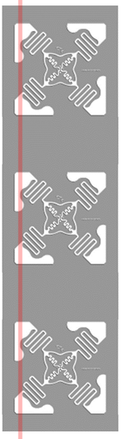
(inlay outline from www.tageos.com)
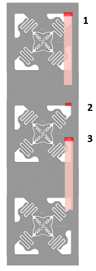
Some inlays (antenna on a transparent liner) may not have a clear trigger path, but the trigger sensor would fire multiple times per inlay. Sometimes the antenna shapes are small compared to the window of view, in this case, even the smallest drift across a lane could be a problem.
In label machines lane speeds are typically tens of meters per minute and can be even hundreds of meters per minute. At high speeds, materials start easily vibrating. If the material happens to jump when the edge is in the window of view, there is a risk of double trigger.
Voyantic Tagsurance 3 system has several built-in features that help with triggering.
The Tagsurance 3 system has features that help in avoiding typical trigger problems. When used correctly, the Tagsurance triggering is 100% reliable.
Tagsurance 3 Triggering Features
The Tagsurance 3 features that help with triggering include:
- Support of multiple sensor types
- Advanced pattern recognition
- Simulated triggers
- Visibility on trigger performance
- Strobe light
Tagsurance 3 Supports Multiple Trigger Types
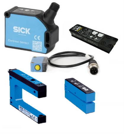
Several types of trigger sensors can be used in the Tagsurance system. All these sensors are plug-and-play compatible with the Tagsurance system.
- Contrast sensors (grayscale or color contrast) recognize differences in color or darkness, such as the edge between a liner and a label, as long as there is a contrast difference.
- Through-beam sensors sense changes in materials’ capability to pass light, as long as some part of the material passes light.
- Capacitive triggering senses edges between metal and non-metal
- Ultrasonic triggers sense differences in material thickness
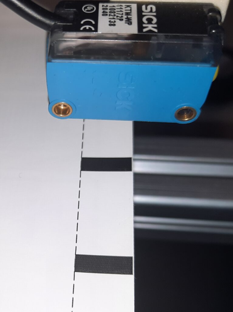
Pattern Trigger
Pattern trigger is a feature that can always be used. Defining a simple pattern has proven to be an efficient way to avoid double triggers regardless of the root cause. It eliminates double triggers arising from complex antenna patterns, varying light conditions, a vibrating liner, and so on.
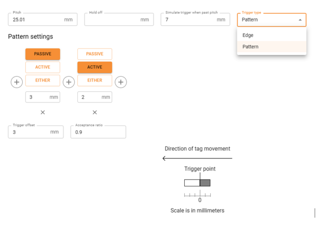
The above picture illustrates settings defining a simple pattern. This pattern replaces a plain edge recognition, by expanding the edge. In this pattern, when the label passes the window of view of the trigger sensor, the sensor must first see 3 mm white, and then 2 mm color (trigger mark). When the defined pattern is seen, the trigger is fired at the actual edge position inside the 5 mm long pattern.
This pattern efficiently eliminates double triggers. If the trigger saw 2 edges – for example, because of liner vibrating, the pattern rule would not be met. This is when simulated triggering comes into play.
Simulated Trigger
In the above settings, the repeat length, aka pitch, is defined to be 25.01 mm, and a simulated trigger is generated after 7 mm has passed from the expected trigger position. The following actions are performed at the expected label position (and not 7 mm off).
The trigger is simulated if the sensor doesn’t fire as expected, regardless of the reason. Reasons for not triggering could be poor-quality printed trigger marks, missing labels, lane drifting, or trigger patterns not matching the set trigger pattern conditions.
The simulated trigger feature fixes most of the issues causing the trigger sensor not to see the edge as expected.
The simulated trigger feature is also used in detecting missing labels.
Hold-off Distance
Another possibility to avoid double triggers is to set a hold-off distance. With this feature, a double trigger is discarded within the hold-off distance. For example, if a 0.5 mm hold-off distance is set, it eliminates most of the double triggers.
Hold-off distance should be used with caution when used to avoid double triggers in complex inlays.
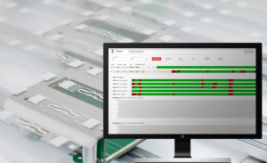
Visibility into Triggering
Tagsurance 3 system provides visibility on trigger reliability. The trigger sensor view shows the actual repeat length as seen by the trigger sensor.
In the above example, there is periodically one repeat that is about 0.5 mm longer than others. This 0.5 mm must be considered when optimizing the trigger position. An additional 0.5 mm safety margin must be used.
In this example, the liner drifted and for a short period, triggers were missed. The scale of the repeat length changes for a while because of the exceptionally long trigger interval. Similarly, double triggers would be observed as exceptionally short trigger intervals.
Strobe Light
For optimizing trigger position Voyantic offers a strobe light that automatically synchronizes with trigger signals. The strobe light flashes whenever a label is in the test position. And because the human eye works as the human eye works, the strobe light shows perfectly where the label is on the coupling element when testing starts. Optimizing trigger positioning becomes easy.

Recommendations – How to Make Triggering Perfect
- Select a sensor type that matches the material.
- Use the pattern trigger feature combined with simulated triggering.
- Confirm reliable triggering with the trigger sensor view.
- Use strobe light to fine-tune the trigger position.
With the above principles, the trigger sensor will work perfectly.
See Tagsurance 3 in Action
Book an online demo
Fill in your details, and we’ll be in touch to schedule an online demo.