I am a Senior Product Manager, passionate about leveraging technology to drive innovation and solve complex challenges in the RFID industry. With a customer-centric approach, I lead cross-functional teams to deliver cutting-edge solutions that exceed market expectations
It’s been a full year since we last shared the latest in our continuous journey of innovation with Tagsurance 3. Over the past year, we’ve been hard at work, rolling out several significant updates and enhancements. Now, let’s dive into the most noteworthy advancements that have propelled Tagsurance 3 forward!
Since our last update, Tagsurance 3 has evolved from version 3.5.0 to 3.12.0. That’s more than 10 releases packed with a combination of major feature introductions, minor enhancements, and diligent defect fixes. Our commitment to excellence ensures that every update enhances the accuracy and reliability of quality control for RAIN RFID product lines, from chip attachment and label converting to offline reel-to-reel items.
Here’s a quick overview of some of the most impactful and requested upgrades we’ve made to Tagsurance 3 over the past year:
Tagsurance has now improved tag response detection
Tagsurance SL UHF can consider a tag bad if the tag response is significantly weaker than the responses used to be for good tags tested by the same Tagsurance SL UHF tester. This response level detection, also called backscatter strength detection, improves the test result quality, especially in multilane processes. In the multilane process, the tester’s sensitive receiver may hear a tag response from the simultaneously tested neighbor tags, but this feature prevents a weak response from being interpreted as a good tag response.
Lot management-related improvements
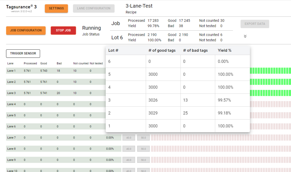
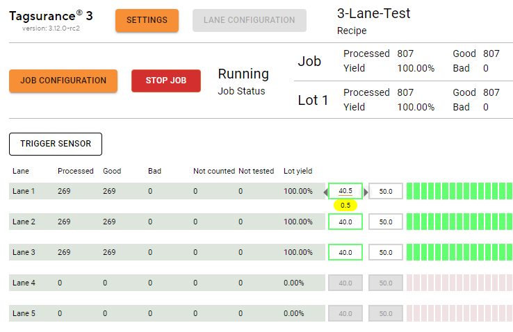
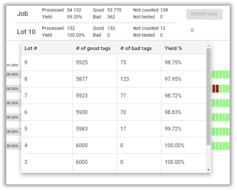
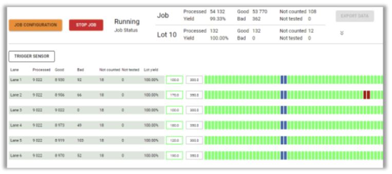
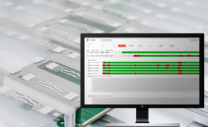
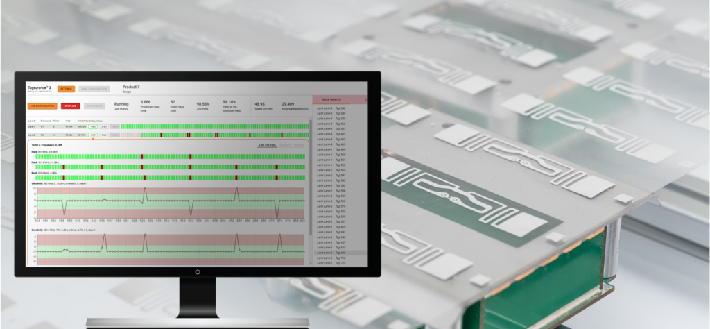
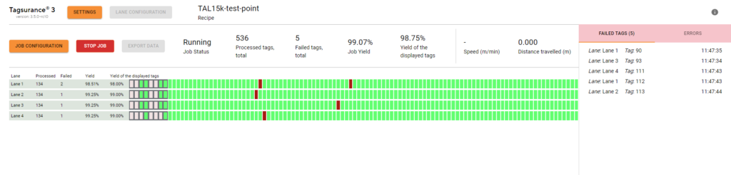
Lot statistics (yield and tag counts) are shown for the current lot. The lot yield is also displayed per lane:
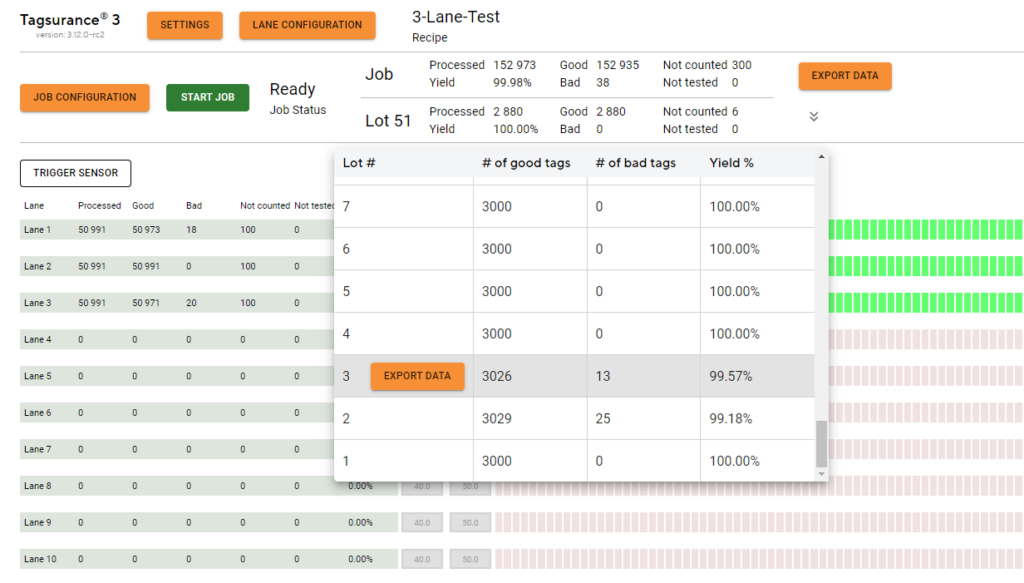
The completed lots are listed with counts and yields and the lot-specific results can be exported:
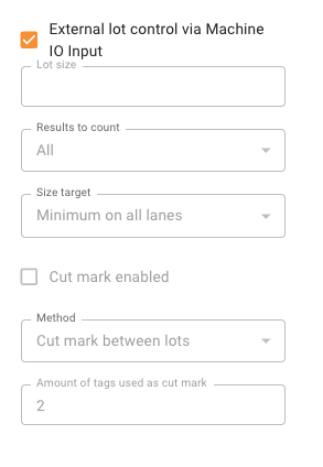
Support for external lot control via machine IO input: Tagsurance 3 supports an external signal for a lot change. It is possible for the production machine, e.g. turret rewinder, to give an IO signal when the liner is cut and the lot is changed. The lot change position is parametric in Tagsurance 3 and the position can be set according to the location where, for example, the liner is cut. The lot number is added to the tag results as before. When an external lot control is enabled, only a limited set of action triggers are available.
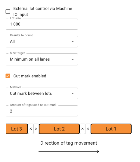
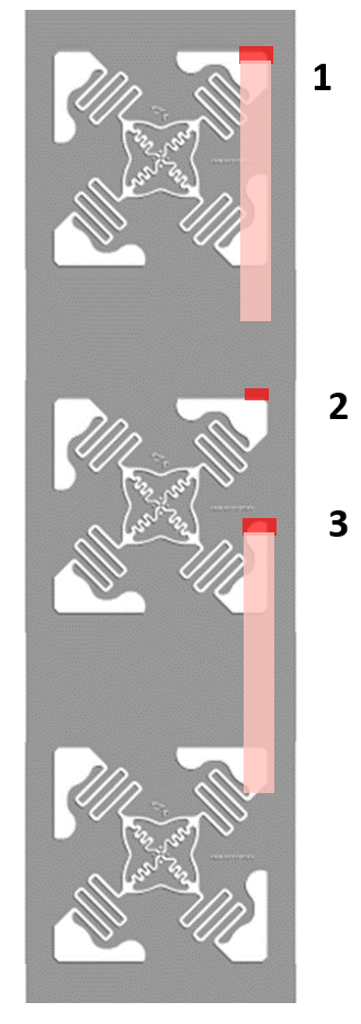
Tagsurance has cut mark feature
Cut mark is a feature that separates lots visually from each other by the markers. Tags marked as cut marks are not counted in any lot.
API trigger in Tagsurance
API trigger enables customers who integrate Tagsurance 3 via APIs to trigger any active device anytime. This feature is enabled only when a new type of job is running. When the API trigger is enabled, all other trigger sources are disabled and only a limited feature set is enabled.
Note: We also plan to bring this feature to operator UI shortly.
IO Only station enhancements
Support for TAL15k jobs: Now three device types: Tagsurance SL UHF, Tagsurance HF, and IO-only devices can be used in systems using TAL15k or DDA serial interface, although one device type at a time.
The delay compensation for IO-only devices added:
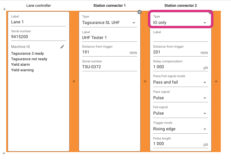
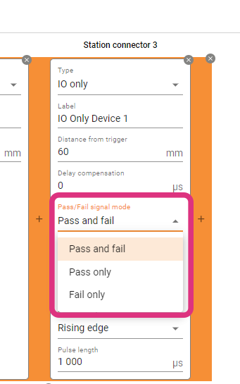
Tagsurance 3 can also support configuring if an IO-only station should return only a pass or fail signal. We have introduced a new configuration option for IO-only stations under lane configuration where an IO-only station can be configured to pulse on passing tags or pulse on failing tags. Users have the flexibility to set the deadline for waiting for a pulse. This can be either until the next trigger or a user-defined timeout value.
Puncher improvement
Tagsurance 3 can now configure a puncher-type station to adjust the puncher trigger pulse duration based on the distance in addition to time. Previously, the puncher station applied pressure against the tags based only on a fixed time duration.
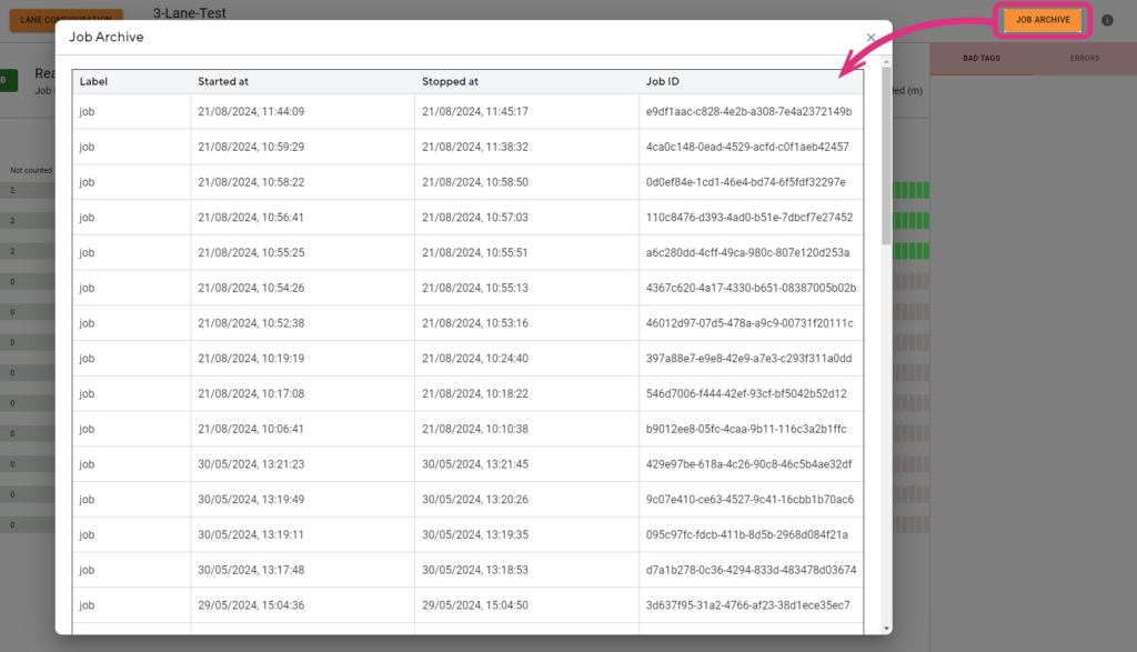
Job archiving
The last 50 jobs (as long as 200 M results in total are not exceeded) can be stored and listed in the Operator UI and their CSV exports can be downloaded; note that the system automatically cleans up jobs from the oldest when the total number of jobs exceeds 50 or total number of stored results exceeds 200 million.
UX improvements
The speed value in the operator UI is shown in red when the machine runs backward and the speed is negative.
The Units Per Hour value is displayed in the operator UI. The UPH is calculated based on the past time window which can be configured in Tagsurance 3 settings.
In operator UI, users can increase the step size of fine-tuning offset by 0.5 mm (instead of the earlier 0.1 mm)
Stay tuned as we continue to innovate and enhance Tagsurance 3. Our dedication to providing unparalleled quality control tools for the RAIN RFID industry remains unwavering. Thank you for being a part of our journey!
Notes: The latest Tagsurance 3 version 3.12.0 can be seen here. If you’re interested in receiving product updates to your email, sign up here!
About the author
Voyantic
Voyantic is a leading provider of testing and encoding systems for the RFID industry. Our solutions are designed to accelerate development, ensure the highest design and manufacturing quality, and ease the adoption of RFID technology.
Today Voyantic announces the end-of-life schedule for the RFID Protocol Analyzer product as follows:
End-of-Life Schedule
The last order date will be Sep 27th, 2024
Tech Support and spare part availability until the end of 2025
New software versions will not be released
For any questions, don’t hesitate to get in touch with your Voyantic Sales representative or send us a message ›
About the author
Anirudh Wali
I am a Senior Product Manager, passionate about leveraging technology to drive innovation and solve complex challenges in the RFID industry. With a customer-centric approach, I lead cross-functional teams to deliver cutting-edge solutions that exceed market expectations
Over the past few years, Voyantic has successfully implemented the Tagsurance 3 quality control system across multiple RFID tag production lines. These integrations not only enable the highest standards in tag manufacturing but also shed light on the positive advancements within the RFID industry. One notable development is the growing synergy between lot management and quality control. For an RFID production manager or quality manager, understanding the quantity of perfectly functioning tags in a delivery is far more meaningful than just having a count and yield percentage.
Incorporating lot management is more straightforward and cost-effective when done in conjunction with the purchase of new production machinery, rather than attempting to implement it post-machine deployment on the factory floor.
What is lot management?
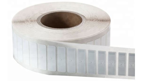
Lot management revolves around the concept of a known quantity of deliverables from a specific process step. In the realm of RFID label production, a lot typically corresponds to one roll of labels.
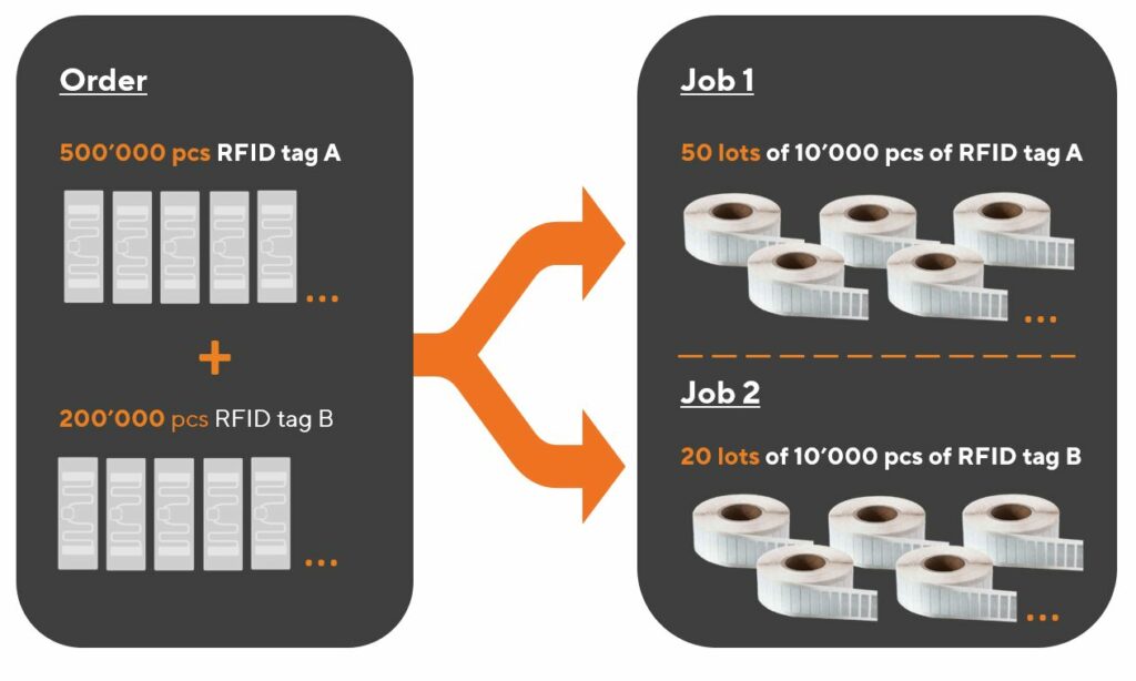
A closely related term is “job.” A job refers to an operation dedicated to producing a specific type of product for a customer or an internal order. Importantly, the process and output remain consistent throughout a job, which may encompass one or multiple lots.
The terminology is easiest to explain with some pictures.
Relation of a lot to an order from a customer, and a job in production.A lot is typically the same as a roll.
Before starting a job in the Tagsurance GUI, it is possible to define the lot. The lot definition includes details such as.
Are all tags counted, or just the good ones?
Is counting across lanes, or on a single lane?
Is the lot change marked with a cut mark?
What should the machine do when the lot is complete?
Lot management
In a typical production setup, where delivery and production are roll-based, lot management includes:
Producing rolls with the desired quantity of labels,
Understanding the quantity of tags within each roll, and
Generating and reporting relevant data for each lot (each roll)
Tagsurance 3 system role in lot management
Tagsurance 3 quality control system plays a pivotal role in the seamless lot management in RFID tag manufacturing. It employs a sophisticated approach to decide whether an individual tag should be counted in the production result set, leveraging comprehensive test data to ascertain the number of tags produced on each lane, differentiating between good and failed tags.
One of the distinctive features of the Tagsurance 3 quality control system is its granular understanding of the location of each tag on the production line. It precisely tracks the lane and the distance from a trigger sensor in millimeters, providing essential position information. This combination of counts and position data serves as the cornerstone for effective lot management.
Given that the Tagsurance 3 quality control system possesses a wealth of information, it becomes the logical and secure choice to entrust with lot management. An alternative approach could involve transmitting count and fail status information to other machine components, such as the machine PLC. However, this introduces unnecessary complexity and potential risks. In high-speed production lines, even a minimal delay in data transmission (from Tagsurance 3 to machine PLC) carries the risk of misaligning counts by a single tag.
The optimal and most efficient solution is allowing the Tagsurance 3 quality control system to take charge of lot management for the following reasons:
Precise Quantity Tracking:Tagsurance 3 is equipped to accurately determine the number of tags in a roll.
Comprehensive Reporting:Tagsurance 3 generates and reports relevant data for each lot, providing a comprehensive overview of passed or failed tags.
When the Tagsurance 3 system manages the production lot information, the risk of split-brain problems between different systems is eliminated. Additionally, Tagsurance 3 offers the flexibility to provide precisely timed signals before, on, or after lot completion, ensuring a smooth and synchronized production process. This level of integration not only enhances operational efficiency but also mitigates the potential risks associated with data transmission delays in a fast-paced manufacturing environment.
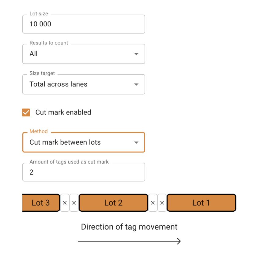
Cut mark
The cut mark serves as a practical tool in lot management, providing a visual demarcation between the end of one lot and the commencement of the next.
Cut marks indicated in Tagsurance 3.
Tagsurance 3 system seamlessly integrates with the manufacturing process, triggering the device responsible for creating cut marks. In many instances, the same device used for marking failed tags is employed for printing cut marks as well.
What does the machine need to handle?
While the Tagsurance 3 system handles various aspects of lot management, the tag manufacturing machine still plays a critical role, particularly in the precise execution of cutting tasks to create the desired rolls.
There are different ways to do this:
Automatic turret rewinders
Some machines incorporate automatic turret rewinders, presenting an efficient solution. In this setup, the production job operates continuously, and rolls are automatically cut to the correct size. This automation eliminates the need for manual roll changes by operators.
Cut mark and manual cutting
In certain scenarios, manual or semi-manual cutting methods prove to be a better alternative. Safety considerations often drive this choice, as automatic cutters need to be well-shielded for the safety ofrom human operators.
In a manual or semi-manual process, the machine halts when the liner reaches the cut position, such as at a splicing table. The operator then manually cuts the liner before seamlessly continuing the process with a new output roll.
This video shows an example of a Turret Rewinder by GM where, at the end of a lot, the machine first slows down and stops, and then an operator cuts the web and finally restarts the machine.
Selecting the appropriate cutting method depends on factors such as safety requirements and the layout of the roll handling area. Whether through automated turret rewinders or manual cutting processes, the tag manufacturing machine’s role in achieving precision and efficiency ensures the delivery of high-quality RFID tags.
Must-have machine features for seamless integration
One indispensable feature that facilitates the seamless integration of lot management with automated testing solutions is a digital IO (Input/Output) input, acting as a control mechanism for the manufacturing machine.
Stop signal input
For efficient lot management, there is a need for precise and controlled stopping mechanisms. Particularly in high-speed machines, abruptly halting operations may compromise accuracy, leading to challenges such as incorrect cutting positions on automatic turret rewinders or misalignment at the splicing table. The inclusion of a digital IO input allows for a controlled cessation of the machine, ensuring accuracy and reliability in the manufacturing process.
Slow down signal input
In practical terms, high-speed machines benefit from a gradual slowing down process before coming to a complete stop. This gradual deceleration is vital for intricate operations, such as ensuring precise cutting positions or accurate alignment at various stages of production. The machine’s ability to receive a digital IO input for initiating the slowdown process enhances the overall control and precision of the manufacturing workflow.
The machine slows down before stopping.
Serial port interface alternative for stop and slow down signals
While digital IO inputs serve as the standard for most machines, it’s worth noting exceptions, such as the utilization of a serial port interface in certain models like the Muhlbauer DDA machines. However, in general, the industry standard leans towards the effectiveness of digital IO inputs for optimal control and coordination between lot management and quality control systems.
Nice-to-have machine features for improved efficiency
Two features that significantly contribute to this efficiency are Cut Mark Capability and Operator Signal Integration.
Cut mark capability
Having a discernible cut mark on labels proves invaluable for human operators, especially when machine stopping accuracy is not within a few millimeters. This visual indicator aids operators in clearly identifying which labels belong to the previous lot and which are part of the next one. Even with automatic turret rewinders, the presence of a cut mark provides operators with peace of mind regarding the correctness of quantities.
The Tagsurance 3 system excels in this aspect, precisely triggering the cut mark at the right position. This feature not only enhances accuracy but also empowers operators with a clear demarcation between lots, ensuring seamless continuity in the production process.
Operator signal
Efficient lot management extends beyond just machine capabilities; it involves effective communication with operators. Even in the case of automatic turret rewinders or manual cutting scenarios, alerting operators when a lot is nearing completion proves invaluable. This proactive approach allows operators to prepare for tasks such as cutting the liner and changing the roll promptly, minimizing machine downtime.
The Tagsurance 3 system takes the lead by providing timely signals, either on lot completion or even a predetermined quantity before completion (e.g., 500 labels before the lot concludes). These signals can be utilized by the machine to trigger visual alerts, such as signal lights, or audible notifications through loudspeakers. This integrated communication ensures that operators are well-informed and can take prompt action, contributing to a more streamlined and efficient RFID tag manufacturing process.
Signal lights alert the machine operator.
Strategic considerations for a label manufacturer to optimize lot management
The seemingly minor features within the production machinery play a pivotal role in the seamless execution of lot management. Features such as
slow down signal input,
stop signal input,
serial port interface on some Muhlbauer DDA machines,
ability to print cut marks and,
ability to signal the operator
might appear subtle, but their absence can pose challenges in implementing effective lot management.
When investing in a new label manufacturing machine, ensure that lot management-related details are explicitly specified. The absence of connectors and signaling means can prevent lot management from working optimally. As RFID technology evolves, these features become indispensable for RFID production and quality managers seeking to elevate standards and achieve greater efficiency in the tag manufacturing process.
Connect with us to learn more about Tagsurance 3 lot management features and integration into production machines.
I am VP, Sales and Marketing at Voyantic. I have over 15 years of experience from the RFID industry in Europe and the USA. I have two master's degrees: in industrial engineering and in marketing, and two patents in auto-ID technology. I am actively participating in RAIN RFID alliance activities.
In the past couple of years, I have been following several projects where the Voyantic Tagsurance systems have been integrated into production machines. Surprisingly often, the biggest problems have been related to triggering – “seeing” accurately when a label enters the system. The experience even turned into a rule of thumb: “If something does not work correctly, first check the triggering”. I have realized that getting the triggering to work correctly is of utmost importance.
At the same time, I have been pleased to see plenty of new Tagsurance features that help to avoid challenges with triggering.
In this article, I will discuss:
Why it is so critical to get triggering to work perfectly?
Why triggering can be difficult?
How do Tagsurance 3 features help get the triggering reliable?
Principle of Triggering
All (or most?) trigger sensors work with the same few simple principles:
Each sensor has a physical parameter it monitors. Depending on the sensor type the parameter can be the strength of light of a certain color (through a beam sensor), amount of conductive material (an inductive sensor), darkness of view (a contrast sensor), darkness and shade of color in view (a color contrast sensor), and so on.
The sensor has a window of view. It only senses the parameter within this window of view.
The sensor is trained/programmed to recognize when the parameter passes a threshold value. For example, if a view of a contrast sensor gradually turns from white to light grey to darker greys and black in the end, the sensor is trained to see a specific point in the continuum as the threshold point.
At the threshold point the trigger sensor’s digital output changes from 1 to 0 (or vice versa, or the trigger sends a pulse).
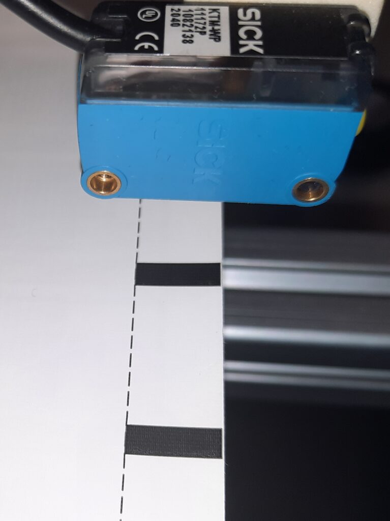
A contrast sensor is designed to see the edge between light and dark areas when the edge passes the window of view. In the sample, the labels have a printed trigger mark to make the triggering easy.
Why does triggering need to be perfect?
Any problem in triggering will affect the overall quality system performance, production machine performance, and production process accuracy and efficiency. Some triggering problems are obvious, some are more subtle.
Missed triggers
Double triggers
Not detecting missing labels
Suboptimal timing
Suboptimal positioning
If a trigger is missed on a tag, that tag flies through the machine undetected. It would not be tested or otherwise processed. It would not be recorded in production logs. It would not be counted to output quantity. But it would be on the roll and get delivered to the customer – free of charge, of unknown quality, and probably incorrectly processed. With a high likelihood, there would be problems awaiting the customer.
A double trigger is an opposite issue. One label is counted twice and attempted to be tested and processed twice. There is a high likelihood that one or both of the process actions fail. The customer would only receive one label instead of the two that were counted. Counts, log files, yield data, and so on would be incorrect.
In some processes, a label can be detached from the liner. Recognizing these missing labels can be important for keeping the entire process optimal. The challenge is to notice when a label does not pass the trigger sensor when expected. A bit of smartness needs to be added to the trigger signals.
In RFID label production machines, there are usually only a few milliseconds to test an individual tag. Accurate results are based on the inlay being at the right position on top of the test coupling element when the test is made.
In this example, a label can move 7 mm on top of the Snoop Pro coupling element while being tested. With 60 m/min lane speed, this gives 7 ms of test time. If 1 mm is wasted because of suboptimal or non-consistent triggering, the test time is reduced to 6 ms (about 14.2% less time available).
Why triggering can be difficult?
The root causes for triggering difficulties vary:
One sensor type may not fit each produced material.
The “edge” may not be clear enough for the sensor in use.
There may be multiple edges per inlay at the path crossing the window of view.
When the liner moves, it may also drift across the lane, or vibrate up and down.
Materials have imperfections.
With fast-moving material, it is not easy to see the exact position of triggering – optimization is difficult.
In RFID label machines typical materials to trigger are:
Inlays
Cut labels
Uncut labels
Cut RFID labels
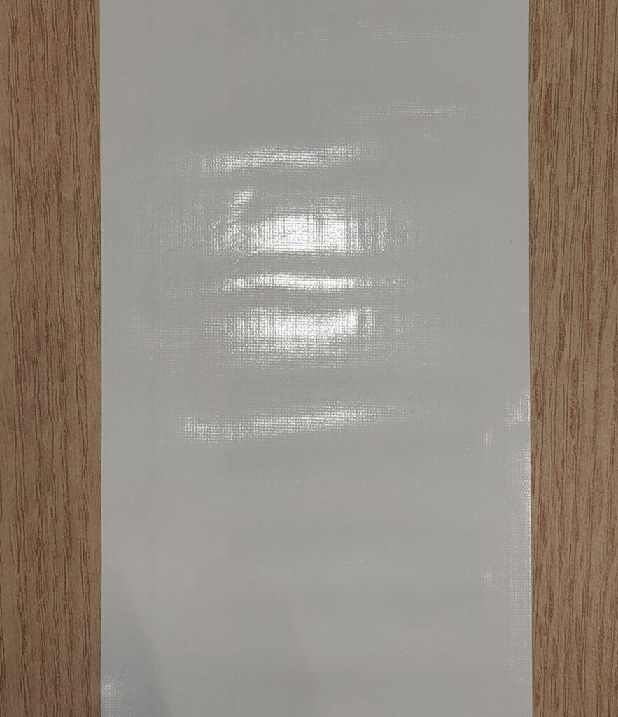
Cut labels are usually the easiest material with clear edges between the label and out of the label. Triggering issues may arise, for example, if lighting conditions change. Glossy materials would amplify the difficulty. The issue is that the threshold position within the window of view can drift if the sensor receives a variable amount of light. If the color of the liner is close to the color of the label, detecting the edge may not work with a contrast sensor.
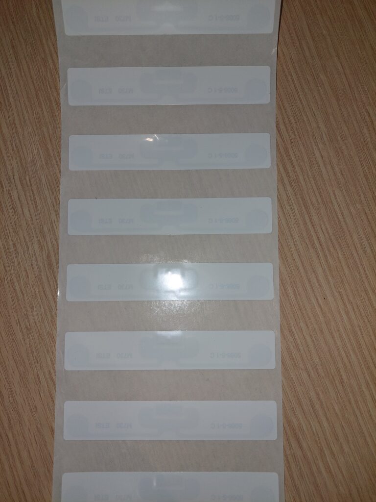
Uncut RFID labels. Note also material being wavy, this is a potential problem for accurate triggering.
Uncut labels without a trigger mark cannot be triggered with contrast sensors. Depending on the material a through-beam sensor or metal sensing inductive or capacitive sensor is needed.
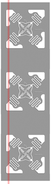
Inlays with no single-edge trigger path (multiple edges per label). (inlay outline from www.tageos.com)
Some inlays (antenna on a transparent liner) may not have a clear trigger path, but the trigger sensor would fire multiple times per inlay. Sometimes the antenna shapes are small compared to the window of view, in this case, even the smallest drift across a lane could be a problem.
Inlays with a clear trigger path (inlay outline from rfid.averydennison.com)
In label machines lane speeds are typically tens of meters per minute and can be even hundreds of meters per minute. At high speeds, materials start easily vibrating. If the material happens to jump when the edge is in the window of view, there is a risk of double trigger.
Voyantic Tagsurance 3 system has several built-in features that help with triggering.
The Tagsurance 3 system has features that help in avoiding typical trigger problems.When used correctly, the Tagsurance triggering is 100% reliable.
Tagsurance 3 Triggering Features
The Tagsurance 3 features that help with triggering include:
Support of multiple sensor types
Advanced pattern recognition
Simulated triggers
Visibility on trigger performance
Strobe light
Tagsurance 3 Supports Multiple Trigger Types
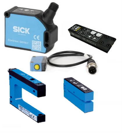
Several types of trigger sensors can be used in the Tagsurance system. All these sensors are plug-and-play compatible with the Tagsurance system.
Contrast sensors (grayscale or color contrast) recognize differences in color or darkness, such as the edge between a liner and a label, as long as there is a contrast difference.
Through-beam sensors sense changes in materials’ capability to pass light, as long as some part of the material passes light.
Capacitive triggering senses edges between metal and non-metal
Ultrasonic triggers sense differences in material thickness
Several trigger sensor types can be used in the Tagsurance 3 system.
Pattern Trigger
Pattern trigger is a feature that can always be used. Defining a simple pattern has proven to be an efficient way to avoid double triggers regardless of the root cause. It eliminates double triggers arising from complex antenna patterns, varying light conditions, a vibrating liner, and so on.
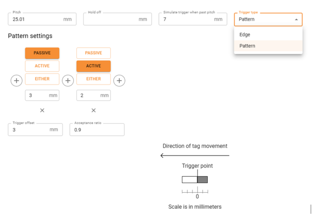
An example of a simple pattern trigger settings.
The above picture illustrates settings defining a simple pattern. This pattern replaces a plain edge recognition, by expanding the edge. In this pattern, when the label passes the window of view of the trigger sensor, the sensor must first see 3 mm white, and then 2 mm color (trigger mark). When the defined pattern is seen, the trigger is fired at the actual edge position inside the 5 mm long pattern.
This pattern efficiently eliminates double triggers. If the trigger saw 2 edges – for example, because of liner vibrating, the pattern rule would not be met. This is when simulated triggering comes into play.
Simulated Trigger
In the above settings, the repeat length, aka pitch, is defined to be 25.01 mm, and a simulated trigger is generated after 7 mm has passed from the expected trigger position. The following actions are performed at the expected label position (and not 7 mm off).
The trigger is simulated if the sensor doesn’t fire as expected, regardless of the reason. Reasons for not triggering could be poor-quality printed trigger marks, missing labels, lane drifting, or trigger patterns not matching the set trigger pattern conditions.
The simulated trigger feature fixes most of the issues causing the trigger sensor not to see the edge as expected.
The simulated trigger feature is also used in detecting missing labels.
Hold-off Distance
Another possibility to avoid double triggers is to set a hold-off distance. With this feature, a double trigger is discarded within the hold-off distance. For example, if a 0.5 mm hold-off distance is set, it eliminates most of the double triggers.
Hold-off distance should be used with caution when used to avoid double triggers in complex inlays.
Use hold-off distance with caution. In the example, an inlay is normally triggered on the first edge, and triggering on the second edge is avoided by setting a hold-off distance (1). But, if a trigger is missed (2), the triggering will permanently go off sync (3).
Visibility into Triggering
Tagsurance 3 system provides visibility on trigger reliability. The trigger sensor view shows the actual repeat length as seen by the trigger sensor.
Trigger sensor view
In the above example, there is periodically one repeat that is about 0.5 mm longer than others. This 0.5 mm must be considered when optimizing the trigger position. An additional 0.5 mm safety margin must be used.
Trigger sensor view – missing label
In this example, the liner drifted and for a short period, triggers were missed. The scale of the repeat length changes for a while because of the exceptionally long trigger interval. Similarly, double triggers would be observed as exceptionally short trigger intervals.
Strobe Light
For optimizing trigger position Voyantic offers a strobe light that automatically synchronizes with trigger signals. The strobe light flashes whenever a label is in the test position. And because the human eye works as the human eye works, the strobe light shows perfectly where the label is on the coupling element when testing starts. Optimizing trigger positioning becomes easy.
When the trigger position is adjusted in the GUI, the trigger mark shift can be observed with the help of the strobe light. (Note that the video with frame rate limitations does not do justice to the strobe light, the real-life view is even better)
Recommendations – How to Make Triggering Perfect
Select a sensor type that matches the material.
Use the pattern trigger feature combined with simulated triggering.
Confirm reliable triggering with the trigger sensor view.
Use strobe light to fine-tune the trigger position.
With the above principles, the trigger sensor will work perfectly.
See Tagsurance 3 in Action
Book an online demo
Fill in your details, and we’ll be in touch to schedule an online demo.
About the author
Voyantic
Voyantic is a leading provider of testing and encoding systems for the RFID industry. Our solutions are designed to accelerate development, ensure the highest design and manufacturing quality, and ease the adoption of RFID technology.
It has been almost a year since the Tagsurance® 3 launch. So we thought it was about time to report what we’ve been up to with Tagsurance 3 product development and tell a bit more about the product vision and next steps.
I summarized the new features since the launch below. These are made based on customer feedback, our learnings from the market and to enable robust industrial-scale quality control on most production lines.
We are committed to providing the best quality control solution for RAIN RFID production lines from chip attachment and label converting to offline reel-to-reel, and even for tagged items. Our focus is on creating a fast, reliable, scalable, future-proof, and modern quality testing solution that is also easy to integrate.
We will continue full-steam ahead on this track.
We are also working on RAIN encoding. It will be a feature in Tagsurance 3 so the same well-known platform, same team, and same ambition will soon cover RAIN encoding as well. The encoding feature can be upgraded to your current or future Tagsurance 3 installations. More information on the release schedule and specifications will follow.
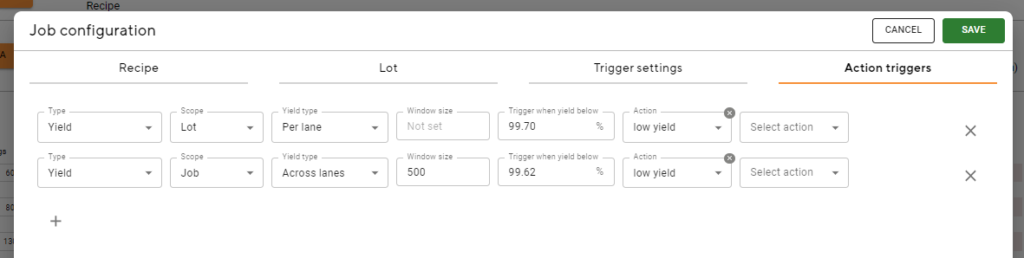
IO signals to the production machine based on yield
This feature brings the possibility to give a digital IO signal to the machine or LED signal tower based on low yield or consecutive failed tags. Here are a few examples:
the yield of current lot/job per lane or across lanes, e.g. lot yield < 99.21 %
the yield of a “window”, e.g.
last 400 tags < 99.1 %
can be used to stop at n consecutive failed tags;
set window size to match wanted “max consecutive fails”
set yield percentage (X) as follows: 0 < X < 1 / [windows size] * 100
Telemetry visible in operator UI
This feature shows lane speed and distance traveled since the job start. You can also trigger sensor-related data in real time:
pattern correlation if the pattern in use
pitch measured based on trigger
IO only station
The IO-only station feature is useful for integrating, for example, a machine vision system for visual quality check or a similar test device that is either triggered by itself or by Tagsurance 3.
The IO-only station works like any other station with the exception that no data connection, no initialization by Tagsurance 3, and no results as data (only pass/fail) in Tagsurance 3.
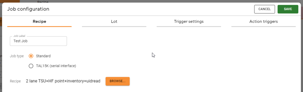
Job configuration in one place
All configuration items (recipe, lot, trigger settings, and action triggers) needed for a job are now in a single modal and easy to manage.
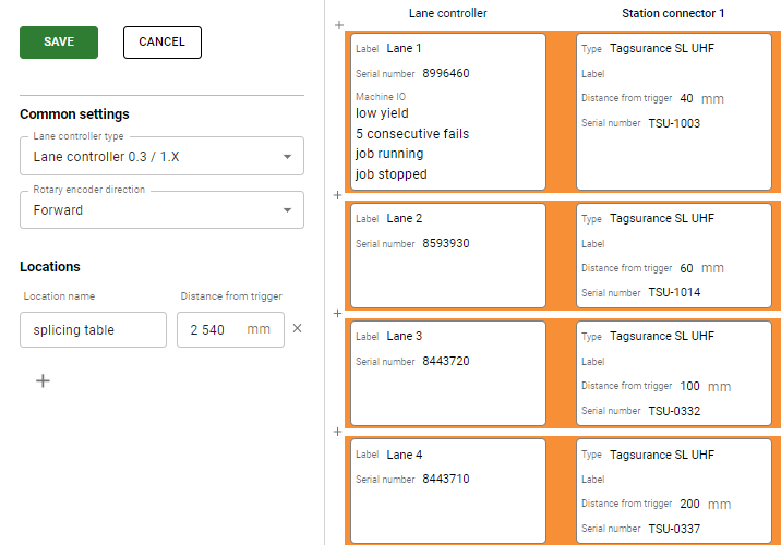
Lane Configurator is now part of the operator UI
The machine IO and Locations settings have been moved to Lane Configurator as well, putting them all logically in the same place.
TAL15k support “RS-232 tester interface”
Tagsurance 3 can be now used with the Mühlbauer TAL15k machines with either one or two testers. The latest version provides full support for the TAL15k including operator UI and a real-time view of how the testing progresses in the testing area.
If your TAL15k has the “RS-232 tester interface” enabled (we will help you to find this out) then Tagsurance 3 can be integrated to TAL15k machines very easily, just by connecting the RS-232 from the machine and changing the coupling elements to Voyantic Snoop Pro.
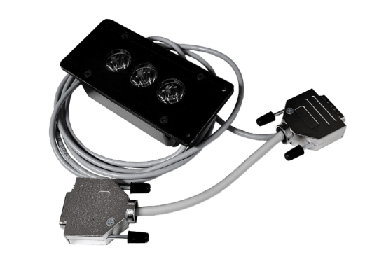
Strobe light (LED) available as an accessory for easy trigger adjustment
The strobe comes with a short adapter cable and it is connected between the “Station IO cable” and the “Station”.
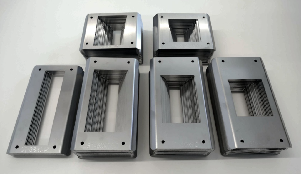
Snoop Pro shielding plate collection has grown significantly
Snoop Pro 1.0 and Snoop Pro Mini 2.0 have now a large collection of shielding plates available to purchase to avoid compromising lane speed and/or testing accuracy. New plates also have the type and opening size engraved on them for ease of use.
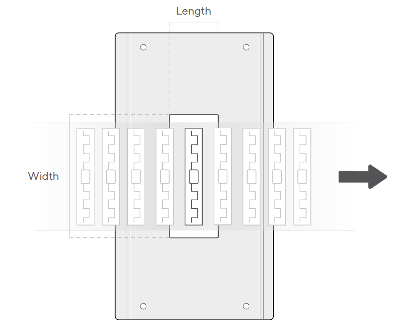
Notes on the terminology:
The length of the shielding plate opening is always the opening dimension in material movement
The width of the shielding plate opening is always the opening dimension perpendicular to material movement
Snoop Pro 1.0 selection:
70 mm width – lengths from 24 to 60 mm in 2 mm steps
90 mm width – lengths from 20 to 60 mm in 2 mm steps
115 mm width – lengths from 24 to 60 mm in 2 mm steps
Snoop Pro Mini 2.0 selection:
60 mm width – lengths from 16 to 60 mm in 2 mm steps
80 mm width – lengths from 16 to 60 mm in 2 mm steps