I am the Co-founder and General Manager of Voyantic, a company that specializes in RFID test and measurement solutions. Before starting Voyantic in 2004, I worked as a researcher at the Helsinki University of Technology focusing on passive RFID sensing for moisture in building structures.
The global use of RAIN RFID is skyrocketing. Application areas are diversifying, and quality requirements are becoming more stringent. At the same time, tags are increasingly integrated directly into products rather than applied as separate labels. Industry pioneer Voyantic believes the next major step in the RFID sector is a shift toward networked, intelligent, and transparent quality management. The company’s latest product release, version 4.0 of Tagsurance® 3, is designed to support this direction.
Key Updates Propel RFID Technology Forward
The new version combines two major advancements: network connectivity and encoding functionality. According to Voyantic General Manager Jukka Voutilainen, these features make it possible to examine the entire RFID production process from a new perspective.
“The combination allows testing and encoding to take place at different stages of production, and the collected data can be integrated into a comprehensive quality management dataset”, Voutilainen explains.
Voyantic’s systems now enable precise measurement of the electrical performance of tags. The encoding feature adds a completely new dimension: verification and management of the data content. At the same time, the system has been designed to scale and connect securely to the internet, enhancing usability in large, cross-company production chains.
Three Trends Shaping the Industry
Voyantic’s development work is guided by a clear long-term vision: RAIN RFID technology has to be reliable and care-free for the end users. Voutilainen identifies three major trends that are steering the industry in the coming years.
The first trend is the integration of tags directly into products. When an RFID tag is embedded directly into the product, such as a tire or a medical syringe, it can no longer be easily replaced or tested outside the product. This means testing must occur not only before integration but possibly afterward as well. In such cases, the cost of failure can be high: a faulty tag may compromise the entire product. Quality assurance must therefore adapt more precisely to different production workflows. The modularity of Tagsurance 3 supports flexible implementation across various processes.
The second trend involves the expansion of quality expectations throughout the supply chain. Traditionally, tag quality has been enforced at chip bonding, the process step where the tag IC is attached to the antenna. It still remains the single most critical production phase. However, the end users see the quality of the tag after it has passed through various process steps, where the tag’s performance may be impacted. In addition, the supply chain often consists of multiple different parties, such as converters and service bureaus. Tagsurance 3 is designed with this in mind: it can collect and combine quality data from multiple production phases, enabling a broad and transparent view of the process.
The third trend is combining multiple data sources to ensure tag quality. Electrical performance alone is no longer sufficient— a tag may seem to work seemingly well but ends up failing prematurely in the end application. Failures like this can be identified and corrected by combining other process data with electrical performance in quality verification. Secondly, the tag also needs to contain correct and reliable information. When encoding is integrated with product data in backend systems, it becomes possible to verify tag authenticity or link it precisely to a specific item or batch. This opens new opportunities in sectors where traceability and data security are essential.
“Tagsurance 3 is built to support these industry shifts. It’s not just a testing device—it is a system that integrates quality, data, and production management in a new way”, Voutilainen says.
The Need for Testing Will Not Decrease—Quite the Opposite
While RAIN RFID tags are already widely used in retail, emerging applications such as logistics, pharmaceuticals, and food products are imposing new requirements on the technology. In these areas, the tolerance for quality issues is minimal, and the importance of quality assurance continues to grow.
“The need for testing will certainly not decrease in the future”, Voutilainen affirms.
According to him, technological development will increasingly be shaped by customer needs and the specific requirements of different industries. The company continues to develop its products in close collaboration with customers and actively contributes to the creation of new industry standards.
“Testing systems must evolve in step with applications and demands. Our role is to be at the forefront of that progress”, Voutilainen concludes.
Voyantic, a global leader in RFID testing solutions, is proud to announce the launch of the new encoding feature for Tagsurance 3 quality testing system. The latest software release enables encoding and quality control of RAIN RFID labels in high-speed production machines with a single system.
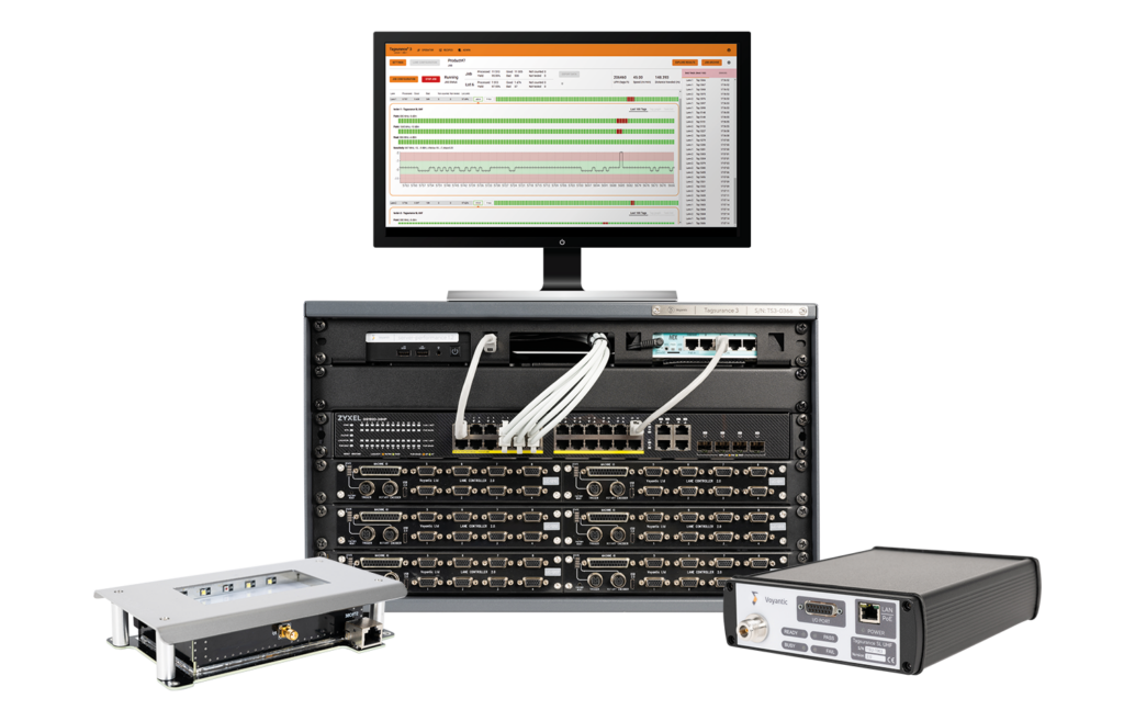
As the demand for RAIN RFID labels is expected to grow exponentially, with billions produced annually, manufacturers need integrated, high-speed systems. The Tagsurance 3 system with encoding feature meets this demand, allowing seamless integration into production lines and eliminating the need for external encoding solutions. The Tagsurance 3 system is modular and scalable and can easily fit into various machine types. The user-friendly, browser-based operating UI helps with adoption at sites.
“At Voyantic, we are committed to delivering cutting-edge solutions that help our customers excel in RFID,” said Jukka Voutilainen, Voyantic’s General Manager. “This upgrade significantly enhances the Tagsurance 3 system’s capabilities, making it a powerful all-in-one solution for RAIN RFID inlay and label production.”
Uncompromised speed and reliability
The Tagsurance 3 system maintains high throughput without compromising the speed and efficiency of the production process. It supports encoding in high-speed machines and can even reach lane speeds for converting machines.
Additionally, the system’s reliability is paramount. Non-encoded, incorrectly encoded, or double-coded labels can create significant challenges for RAIN RFID users. To address this, the Tagsurance 3 system is designed for continuous, error-free operation during extended production runs, ensuring the highest reliability standard in large-volume manufacturing.
Main specifications:
One encoding station per lane is supported
“BlockWrite” data to any writeable tag memory and lock the tag memories (Reserved, EPC, User)
Supported ISO 18000-63 (EPC Gen2v3) commands
BlockWrite
Lock
Read
1-12 lanes
Lock the selected memories permanently
Verify the data is correctly encoded (Read test with verification)
The commercial release of the Tagsurance 3 encoding feature, available starting 10th of April, will be offered as a separate license on top of the existing Tagsurance 3 system. A hardware version 4.x is required to utilize this feature.
I’m a seasoned B2B marketer currently exploring the world of RFID. My passion lies in people and creating efficient organizations, but as a bit of a tech geek, I’ve always been fascinated by technological innovations and marketing tech.
Voyantic recently launched a new version of the Tagsurance 3 system, an inline quality testing system for RFID tag production. With this update, we recommend that customers using the latest version (4.x) keep their systems always connected online. On the other hand, older versions (3.x) should still stay offline. But why the switch? And what benefits come with this new online connectivity?
Let’s dive in!
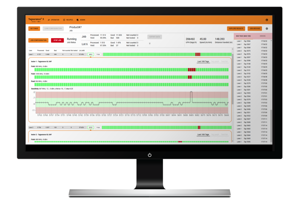
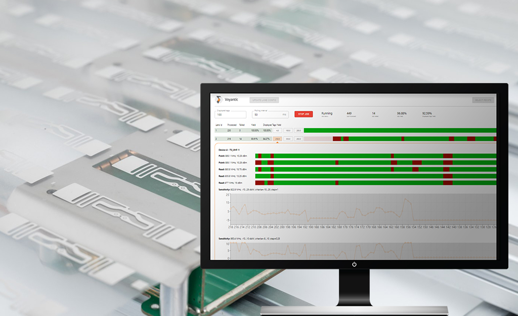
A screenshot of Tagsurance 3 Version 4.x software user interface.
With the new version, the Tagsurance 3 system’s architecture has been completely revamped under the hood. The Voyantic team has carefully designed this upgrade with the future and information security in mind. This release marks an important milestone, enabling safe network connectivity for the test system. Voyantic designs its systems using secure development best practices, and regular third-party audits ensure any identified issues are promptly addressed.
The Tagsurance 3 Version 4.x with online connectivity paves the way for future possibilities, including upcoming encoding operations through the same setup. Enabling encoding will only require purchasing a software license, with no need for additional hardware upgrades.
Simpler, faster, and more efficient—whether it’s for daily use or maintenance tasks
Connecting the system to the internet is safe and recommended for unlocking a range of new features. Today, the concrete updates are most noticeable in the new browser-based user interface, which administrators and operators can access from any computer. Let’s examine the latest features designed to ease the system’s use.
1. Update software directly in the user interface
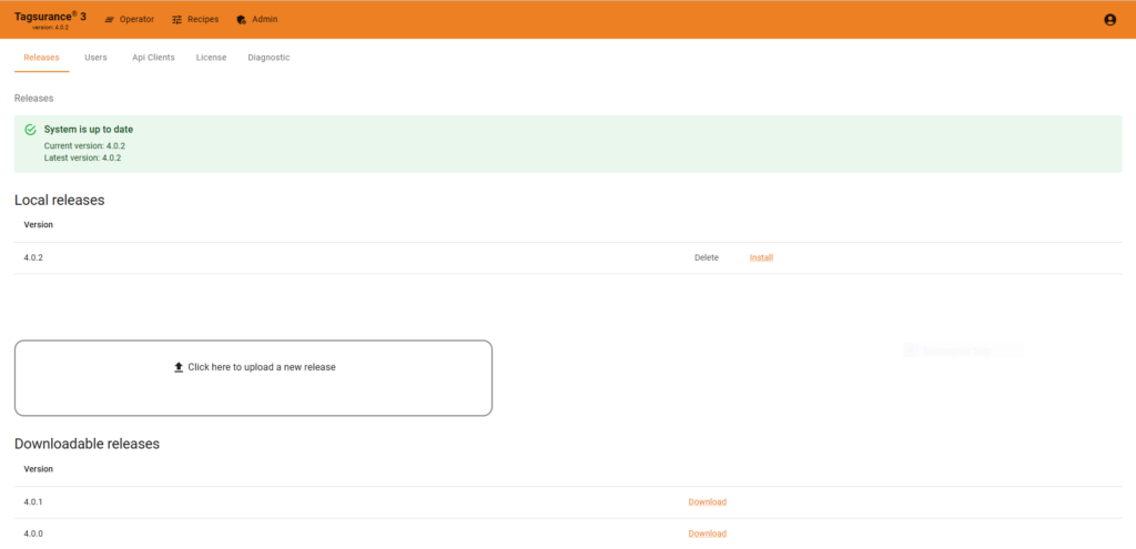
Gone are the days of downloading software update packages separately from voyantic.com and manually performing updates. With this new feature, admins can download and install the latest software versions directly from the user interface via the admin panel—as long as the system is connected to the internet. This ensures your system stays effortlessly updated with the latest features and improvements.
Updating your Tagsurance 3 Version 4.x software has been made easy.
2. Simplified licensing
When your Tagsurance 3 version 4.x system is connected to the internet, it automatically connects to Voyantic’s license server and fetches the license information. Admin users can see all the essential details in the browser-based admin panel, including how long the license is valid, the number of lanes, and Tagsurance stations. It’s all there in one place, making it easy to manage your licensing.
3. Enhanced support
While we hope you don’t need to use this feature, we’ve significantly improved support for the new version. Suppose the system is connected to the internet, and you run into an issue. In that case, it’s now possible to download and send diagnostic files directly to the Voyantic support team through the admin panel. This helps speed up troubleshooting and resolution by providing our team with more accurate data with which to work. Ultimately, this reduces system downtime and takes the headache out of maintenance.
In summary
In the future, online connectivity of the new Tagsurance 3 version will open new business opportunities with the comprehensive management of quality data. Today, online connectivity improves usability and maintenance. It simplifies tasks, adds more features to the user interface, and provides a more efficient way to share information directly with Voyantic.
That said, online connectivity is still optional. Version 4.x systems can also operate offline like the 3.x systems. If you prefer to stay offline, you can still upload software releases and license files from a local computer through the admin panel.
I’ve been working at Voyantic since January 2019, nowadays I work as a Senior HW Designer in our HW team. I do mainly RF and electronics design for our products, but I also know something about mechanics, programming and business administration. Sometimes I feel surprisingly extroverted and might even speak in a webinar or write a blog post.
We continuously seek to improve our products to answer your needs, like making your job easier with user-friendly test systems or improving testing quality. This time, we made some nice improvements to Snoop Pro, one of the components used in the Tagsurance 3 system. The Snoop Pro 2.0 has:
Improved unit-to-unit RF performance variance
Integrated strobe feature
Smaller size and better usability
The improvements were made with backward compatibility in mind to make Snoop Pro 2.0 almost a drop-in replacement for Snoop Pro 1.x, which means:
RF backward compatibility: when testing tags/inlays, the test results with Snoop Pro 2.0 are within the test results variance of Snoop Pro 1.x
Mechanical backward compatibility: Snoop Pro 2.0 has the machine integration attachment holes at the same positions as Snoop Pro 1.x, and also the same shielding plates can be used
Let’s check it out.
Improved RF performance variation with RF backward compatibility
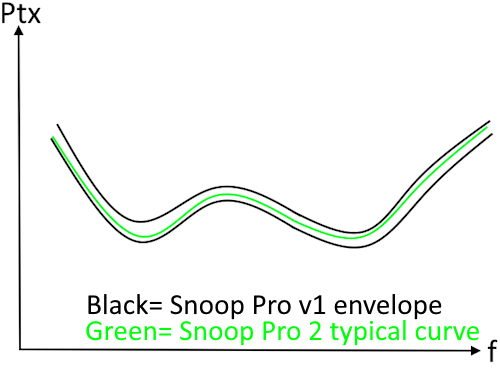
I’m starting with the RF performance because I just love RF. A nice new feature for the Snoop Pro 2.0 is the improved variance, making the produced units more uniform in RF performance. This means that if you test one tag with multiple different Snoop Pro 2.0, the results are very similar.
Illustrated example of the RF backwards performance.
Why is this so nice? I’m so glad I asked. It’s nice because if you want to use identical recipes for different production lines or even factories, the Snoop variance does not prevent doing that. So, better testing quality for your products. However, keep in mind that Snoop is only one of the components in the system; other things, such as the environment near the Snoop or cabling, might still have too much effect.
One of the most important requirements was the RF backwards compatibility so one can replace a Snoop Pro 1.x with the Snoop Pro 2.0 and be done with it. Our definition of RF backwards compatibility is as follows:
With the Snoop Pro 2.0, measured results are within the variance of Snoop Pro 1.x results OR within ±1.0 dB from the center of the Snoop Pro 1.x result envelope average
The difficult part is that the Snoop is always used with a tag/inlay on top of it and together they form a complex structure where every part plays a role. Since all tags/inlays are different and are affecting the Snoop differently, an excessive amount of measurements was performed to make sure we have covered most of the imaginable situations. Especially large tag models couple with the Snoop strongly and have an effect on the performance. Bah, physics and its precious laws.
Voyantic offers different kind of extensions for Snoops and those are compatible with the Snoop Pro 2.0. However, for the extensions there is no backwards compatibility in RF performance even though the results are close.
Integrated strobe feature
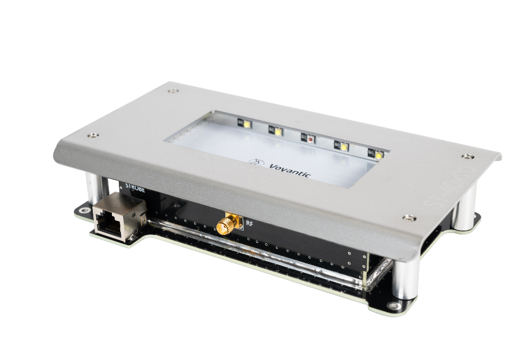
The Snoop Pro 2.0 has a built-in strobe functionality that can be turned on/off with a switch. White LEDs illuminate the trigger position (the moment when the testing/encoding starts), and red LEDs show tags/inlays that are failing the tests.
With the strobe light coming from below the material under test, the strobe is more effective than when the light comes from above. In a Tagsurance 3 system, the Snoop strobe shares a station connector with a TSU, so there’s no need to configure a new station to get it working. The Snoop Pro 2.0 can also be used without connecting the strobe cable; it does not affect the RF performance. The new RJ45 connector was added for the strobe functionality (don’t be fooled by the connector; no ethernet traffic there).
New size, looks, and usability
The Snoop Pro 2.0 no longer wears green; it now has a black-and-white appearance and a slightly reduced size. The new color was picked because of the integrated strobe functionality; white reflects the most light, which is essential for the strobe.
Snoop Pro 2.0 appearance.
With a careful redesign, we could replace the large external RF splitter and the two blue RF cables, making the size of the Snoop more compact. This helps a bit when trying to fit many Snoops in a multilane system where the space is limited.
The magnets were also renewed so less force is needed to change the shielding plate and you don’t not accidentally rip off the copper gaskets during the changing. Less hassle is always nice.
Conclusion
With the backwards compatibility, you can easily integrate the new Snoop Pro 2.0 to your testing systems. With the strobe integrated into the Snoop it is easy to use and doesn’t require additional configuration in the Tagsurance 3 recipe. The improved unit-to-unit variance allows you to more easily use identical recipes between lanes. All with the new Snoop Pro 2.0.
Voyantic announces the launch of a new version of Tagsurance 3 system, an inline quality testing system for RFID tag production. The launch of Tagsurance 3 Version 4.x marks a significant upgrade to the previous version 3.x systems with exciting new capabilities and enhanced usability. This release introduces cloud-based features and lays the groundwork for future functionalities, including encoding operations using the same setup.
The new Tagsurance 3 Version 4.x architecture is designed with the future in mind, unlocking powerful cloud-enabled features. The online connectivity streamlines maintenance work by enabling effortless software updates, simplified license renewals, and enhanced support: diagnostic data can be shared directly with the Voyantic support team for faster troubleshooting and minimized downtime. With this version, Voyantic recommends keeping Tagsurance 3 systems always online to fully leverage the benefits and ensure maximum system efficiency.
Tagsurance 3 Version 4.x also introduces a new browser-based user interface, allowing operators to access the system conveniently from any computer. This eliminates the need for certain peripherals and allows users to connect to the system via a web browser for an intuitive and modernized user experience.
The update also provides a more compact hardware setup, reducing the footprint of controller racks. The new version uses the upgraded Lane Controller 2.0 and the new Server Panel.
Tagsurance 3 Version 4.0 offers backward-compatible APIs that ensure seamless integration with existing systems, safeguarding previous investments and reducing implementation time. Recipes created in previous Tagsurance 3 Version 3.x systems will also continue to work seamlessly, enabling a smooth transition without disrupting existing workflows.
Contact sales@voyantic.com for more information about upgrading your existing Tagsurance 3 system or starting your journey with Voyantic towards improved tag quality.
How Does Antenna Choice Impact Your RAIN RFID System?
Selecting the right antenna can make or break the performance of a RAIN RFID system. Our recent webinar on October 10, “Choosing the Right RAIN RFID Antenna”, provided a deep dive into the critical aspects of antenna selection for RAIN RFID systems.
We explored the fundamental principles of antenna choice, essential parameters to consider, and ways to match antenna features with specific application needs.
The webinar featured insights from industry experts including Daniel Eisen, RFID Engineer at Times-7, Jos Kunnen, CTO at Times-7, along with Sami Rautanen, Senior Hardware Designer, and Teemu Ainasoja, Sales Director, both from Voyantic.
Together, they shared valuable insights into antenna fundamentals, best practices, and considerations for optimizing RFID system performance.
Key Highlights of the Webinar
Key Factors in Antenna Selection
RF Fundamentals in RAIN RFID Systems
Choosing the Best Antenna Polarization for Your Needs
Practical Advice for Antenna Selection
Questions to Ask Your Antenna Supplier
Key Factors in Antenna Selection
Every application has unique requirements, so understanding the essential factors in antenna selection is crucial. Our speakers discussed parameters like frequency, wavelength, and RF (Radio Frequency) characteristics, all of which affect how antennas interact with RFID tags in various environments.
Frequency and radiation pattern: Each antenna has an operating frequency. RAIN RFID operates in 860 – 960 MHz, so make sure you choose the right antenna for your reader. Understanding the radiation pattern is important in order to read the datasheet and select the best antenna for your application.
RF Characteristics: Factors such as RF field strength and energy distribution influence how well an RFID system reads tags, especially in environments with metal, liquids, or other RF interference sources.
RF Fundamentals in RAIN RFID Systems
RAIN RFID technology relies on RF signals in the UHF range of 860-960 MHz. Understanding the behavior of these signals is key to optimizing system performance.
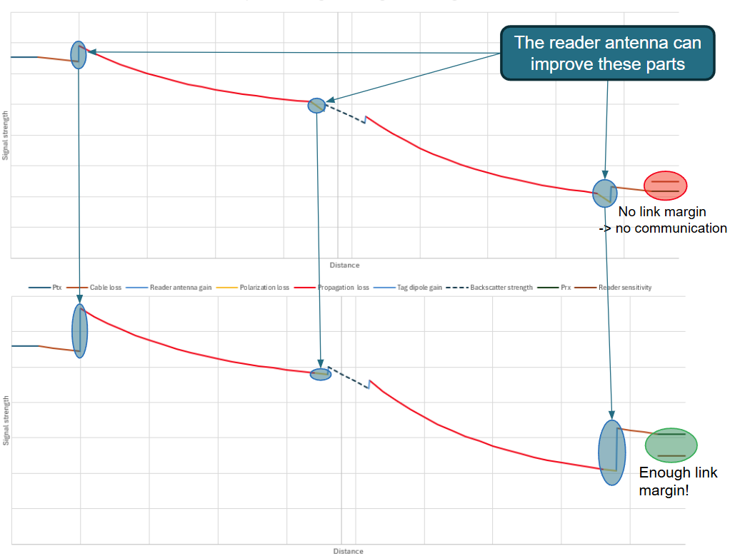
Link Budget: Losses in the RF link may cause excessive signal loss and destroy system performance. This problem can be solved with a right reader antenna with a suitable radiation pattern and polarization.
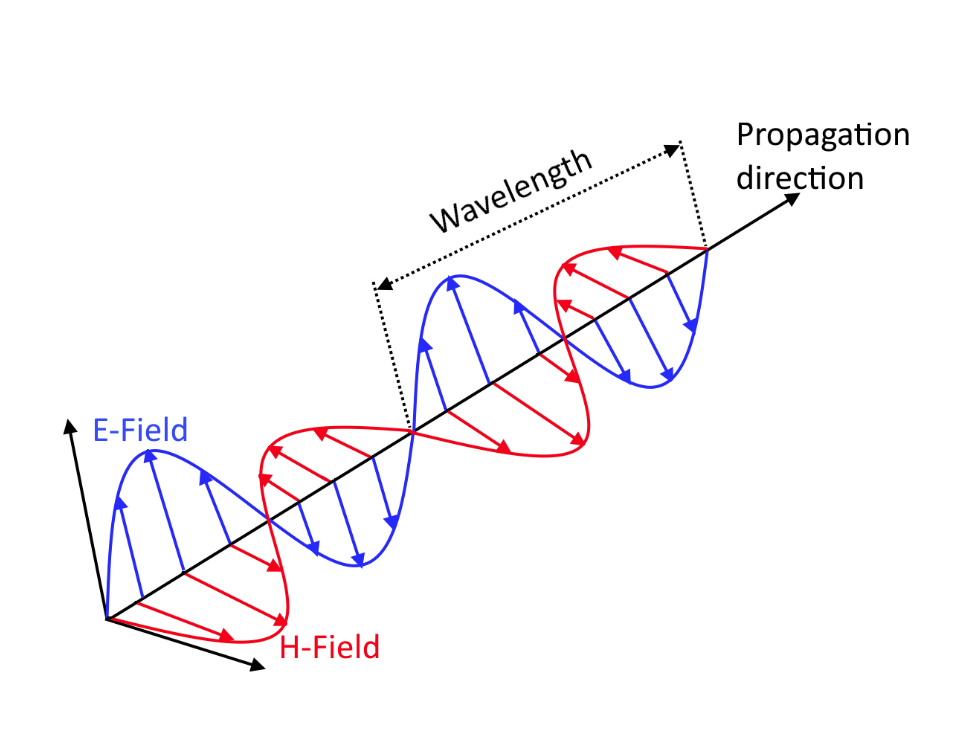
Signal Polarization: The webinar explained how linear and circular polarization can impact read accuracy and range. Linear polarization works well for specific orientations, while circular polarization offers flexibility for tags at various angles.
Choosing the Best Antenna Polarization for Your Needs
Polarization is central to antenna effectiveness. Our experts explained how different polarization types function and when to use each based on application requirements.
Linear Polarization: Suitable for applications where tags are consistently aligned with the antenna. It provides strong signals in a specific direction, ideal for scenarios with controlled orientation.
Circular Polarization: A versatile choice when tag orientation is unpredictable, as it allows signals to be read from various angles. This reduces errors in environments like retail, where items may shift.
Practical Advice for Antenna Selection
Our webinar offered practical tips for balancing gain, beamwidth, and radiation patterns—critical parameters that influence coverage and reliability.
Gain: Higher gain antennas provide a stronger, focused signal ideal for long-range reads, whereas low-gain antennas are better suited for wider coverage in close proximity setups.
Beamwidth and Radiation Patterns: These factors determine how broadly the antenna transmits signals. For example, narrow beamwidth is optimal for focused, direct reads, while a wider beam is suitable for scanning larger areas with multiple tags.
Questions to Ask Your Antenna Supplier
To conclude, our experts provided a checklist of questions to ask when selecting an antenna supplier. Knowing terms like dBi, EIRP, and ERP, as well as understanding compliance requirements, allows you to make informed decisions that ensure efficiency and regulatory alignment.
dBi (Decibel Isotropic): A measure of an antenna’s gain compared to an idealized isotropic antenna. Higher dBi indicates a more focused signal.
EIRP (Equivalent Isotropically Radiated Power) and ERP (Effective Radiated Power): These metrics help determine the actual power output and range capacity, both essential for meeting regulatory standards.
Watch the Webinar On-Demand
Did you miss the live session? You can still access the full recording here.
The webinar is packed with expert insights to help you make confident, data-driven decisions for your RAIN RFID applications.
I am a Senior Product Manager, passionate about leveraging technology to drive innovation and solve complex challenges in the RFID industry. With a customer-centric approach, I lead cross-functional teams to deliver cutting-edge solutions that exceed market expectations
Content
It’s been a full year since we last shared the latest in our continuous journey of innovation with Tagsurance 3. Over the past year, we’ve been hard at work, rolling out several significant updates and enhancements. Now, let’s dive into the most noteworthy advancements that have propelled Tagsurance 3 forward!
Since our last update, Tagsurance 3 has evolved from version 3.5.0 to 3.12.0. That’s more than 10 releases packed with a combination of major feature introductions, minor enhancements, and diligent defect fixes. Our commitment to excellence ensures that every update enhances the accuracy and reliability of quality control for RAIN RFID product lines, from chip attachment and label converting to offline reel-to-reel items.
Here’s a quick overview of some of the most impactful and requested upgrades we’ve made to Tagsurance 3 over the past year:
Tagsurance has now improved tag response detection
Tagsurance SL UHF can consider a tag bad if the tag response is significantly weaker than the responses used to be for good tags tested by the same Tagsurance SL UHF tester. This response level detection, also called backscatter strength detection, improves the test result quality, especially in multilane processes. In the multilane process, the tester’s sensitive receiver may hear a tag response from the simultaneously tested neighbor tags, but this feature prevents a weak response from being interpreted as a good tag response.
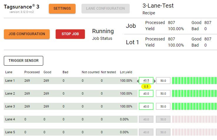
Lot management-related improvements
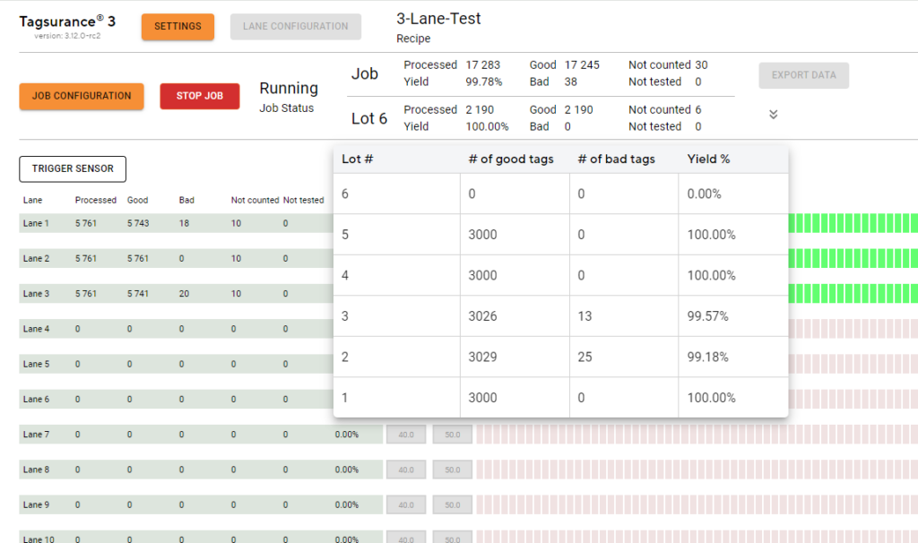
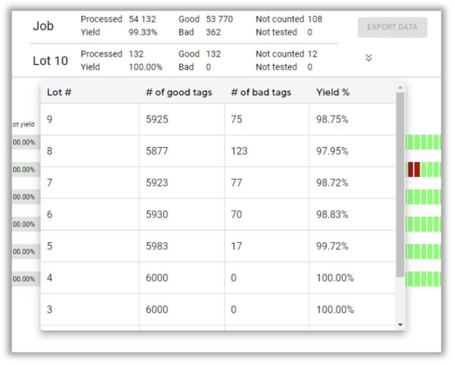
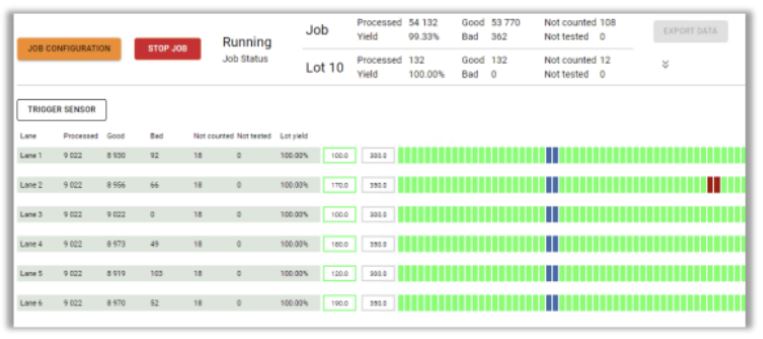
Lot statistics (yield and tag counts) are shown for the current lot. The lot yield is also displayed per lane:
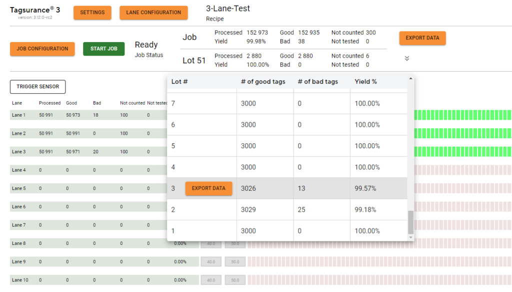
The completed lots are listed with counts and yields and the lot-specific results can be exported:
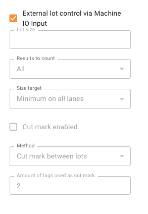
Support for external lot control via machine IO input: Tagsurance 3 supports an external signal for a lot change. It is possible for the production machine, e.g. turret rewinder, to give an IO signal when the liner is cut and the lot is changed. The lot change position is parametric in Tagsurance 3 and the position can be set according to the location where, for example, the liner is cut. The lot number is added to the tag results as before. When an external lot control is enabled, only a limited set of action triggers are available.
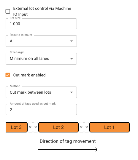
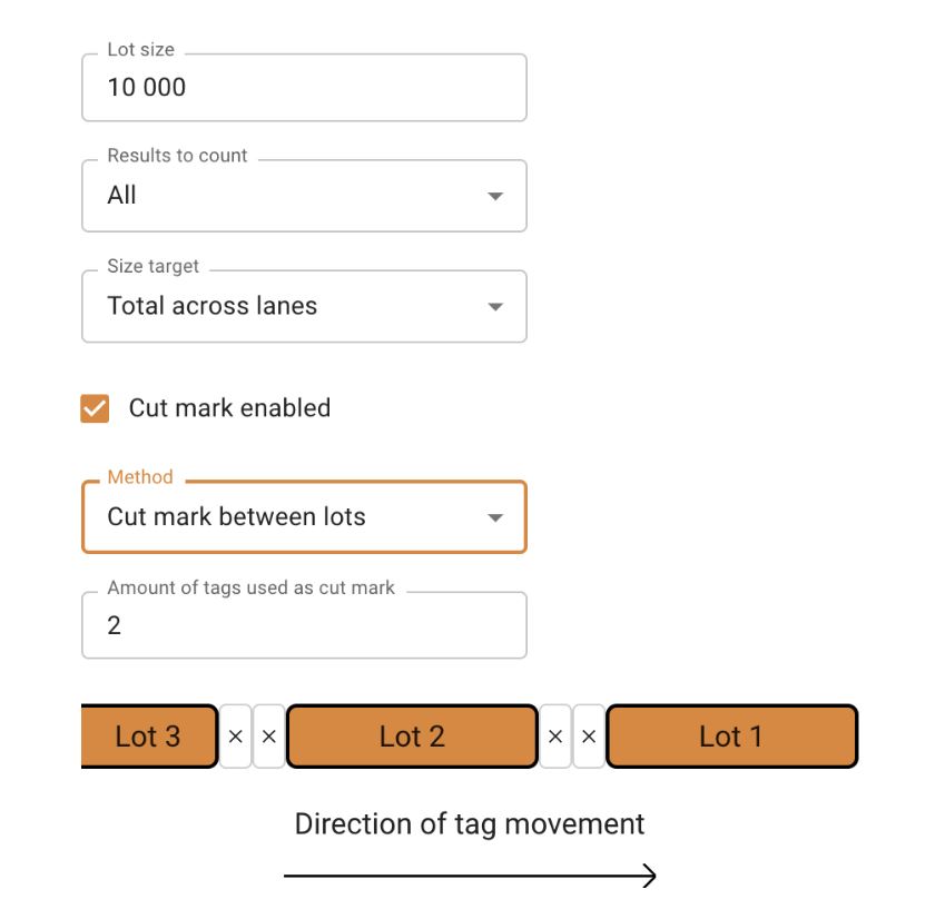
Tagsurance has cut mark feature
Cut mark is a feature that separates lots visually from each other by the markers. Tags marked as cut marks are not counted in any lot.
API trigger in Tagsurance
API trigger enables customers who integrate Tagsurance 3 via APIs to trigger any active device anytime. This feature is enabled only when a new type of job is running. When the API trigger is enabled, all other trigger sources are disabled and only a limited feature set is enabled.
Note: We also plan to bring this feature to operator UI shortly.
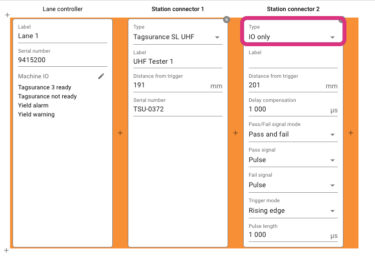
IO Only station enhancements
Support for TAL15k jobs: Now three device types: Tagsurance SL UHF, Tagsurance HF, and IO-only devices can be used in systems using TAL15k or DDA serial interface, although one device type at a time.
The delay compensation for IO-only devices added:
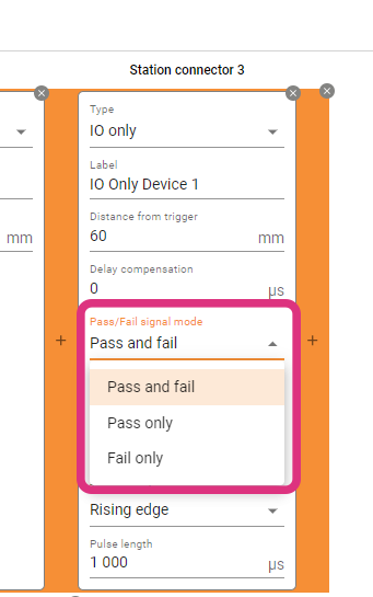
Tagsurance 3 can also support configuring if an IO-only station should return only a pass or fail signal. We have introduced a new configuration option for IO-only stations under lane configuration where an IO-only station can be configured to pulse on passing tags or pulse on failing tags. Users have the flexibility to set the deadline for waiting for a pulse. This can be either until the next trigger or a user-defined timeout value.
Puncher improvement
Tagsurance 3 can now configure a puncher-type station to adjust the puncher trigger pulse duration based on the distance in addition to time. Previously, the puncher station applied pressure against the tags based only on a fixed time duration.
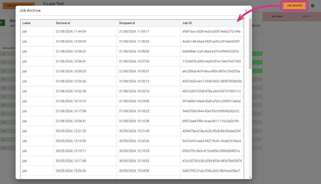
Job archiving
The last 50 jobs (as long as 200 M results in total are not exceeded) can be stored and listed in the Operator UI and their CSV exports can be downloaded; note that the system automatically cleans up jobs from the oldest when the total number of jobs exceeds 50 or total number of stored results exceeds 200 million.
UX improvements
The speed value in the operator UI is shown in red when the machine runs backward and the speed is negative.
The Units Per Hour value is displayed in the operator UI. The UPH is calculated based on the past time window which can be configured in Tagsurance 3 settings.
In operator UI, users can increase the step size of fine-tuning offset by 0.5 mm (instead of the earlier 0.1 mm)
Stay tuned as we continue to innovate and enhance Tagsurance 3. Our dedication to providing unparalleled quality control tools for the RAIN RFID industry remains unwavering. Thank you for being a part of our journey!
Notes: The latest Tagsurance 3 version 3.12.0 can be seen here. If you’re interested in receiving product updates to your email, sign up here!
Recently, we had the pleasure of having James Guzzo from Impinj and Hannes Jehle from DELO present at our webinar on the intricacies of the RAIN RFID IC attach process. The webinar covered the numerous process variables that impact the quality and performance of the inlay, how IC manufacturing recipes can be used in the production process, and the critical role of process monitoring.
Bonus Q&A – Questions Not Answered During the Live Session
The webinar topic proved to be a popular one. The presenters received so many questions during the webinar that the time ran out to cover all of them. So, we followed up with Hannes and James with a few of the questions that were not answered during the live session.
(I recommend you watch the webinar recording before reading the rest of this blog.)
Q1: How do we ensure the accuracy of IC positioning in the process?
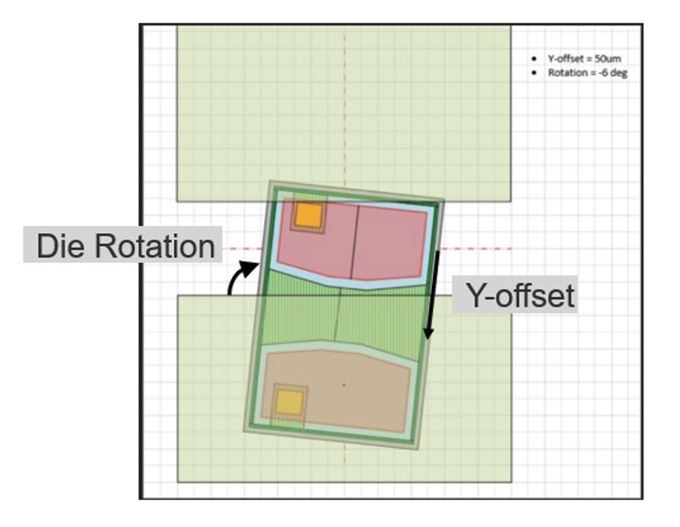
James Guzzo: The single biggest way that you can ensure the accuracy of the IC position is to turn on the DDA Vision system statistics (postplace.rep) and monitor the machine die ejection accuracy and adjust the DDA settings to improve the die ejection/placement accuracy if needed. There are two key parameters the DDA reports on which are the Y-offset (measured in microns) which is the shift up or down of the IC relative to the antenna gap. The second parameter is the die rotation left or right relative to a perfect alignment to the antenna gap (measured in degrees).
The Inlay assembly process allows for a certain level of inaccuracy in the Y-offset and Die rotation and will still produce a reliable, electrically well-performing inlay. The amount of Y-offset and die rotation tolerable is a function of the actual measured (actual) antenna gap and the size of the IC and the size of the IC pads.
There is the possibility that the die can shift or spin in the epoxy dot post-vision system inspection, but we have found the dominant factor in die placement accuracy occurs during die ejection off of the tape. The Voyantic Tagsuance inline electrical test yield generally correlates well with the postplace.rep placement accuracy.
Factors that impact the die placement accuracy and can be tuned to improve die placement: Die Ejector Needle Selection (needle tip radius and angle), dicing tape expansion, DDA die Ejection parameters(Cap Gap, Cap Retract, needle offset, vacuum delay,…)
Q2: Do you have any suggestions about the shape and also size of the die landing area? And what about the gap, previously you shoved 150um for the M800 series (talking about a “standard” antenna).
James Guzzo: See the response to Question 1 above for Context.
Ways to improve the maximum placement tolerance: Reduce the actual antenna gap of your antenna design by reducing your drawn antenna gap. Previously most etched Al on PET inlay manufacturers allowed a minimum drawn 140um and the stated actual gap tolerance is +/-50ums to the drawn. However many manufacturers typically do better than this and are closer to a +40um/-30 based on sampling and measuring actual antenna gaps for several models of inlays.
Numerous etched Al antenna on PET manufacturers now allow a minimum drawn antenna gap of 110um-120um drawn gap and correspondingly are able to achieve actual(measured) antenna gaps of 130um – 160um depending upon the antenna layout and geometries.
Q3: There is much recent talk or hype of “trillions” of RAIN RFID inlays per year to be made, presumably requiring thousands of chip-attach machines. What is the hourly capacity of the highest-capacity IC placement machine?
James Guzzo: The current state-of-the-art direct die attach machine models can create 40k, 80k, and up to 100k inlays per hour.
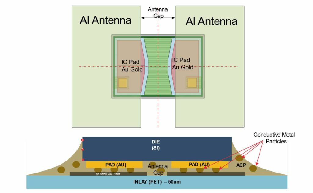
Q4: What is the allowed residue thickness between the gold pad and the aluminium for a proper connection – the thickness the gold particles can bridge?
James Guzzo: The electrical connection between the Tag ICs gold pads and the etched Aluminum Antenna Leads are actually made through the 3-8um diameter metal particles that are in the ACP (Anisotropic Conductive Paste). Different ACPs have different size particles of different conductive materials (e.g. tungsten, nickel, etc.) When the IC is bonded there are two hot pieces of metal in the Die attach machine (Called thermodes) that press against the back side of the die (from the top) and the bottom of the PET inlay. The thermodes accomplish 2 goals: The first is to push the conductive metal fragments into the gold pads and the Al antenna leads and the second goal is to cure or harden the Epoxy. One of the “Bonding” parameters is how much force the thermodes push the die into the inlay. The typical Thermode Bond Force is 1.5 Newtons to 2.5 Newtons.
Inlay bottom and cross-section view.
Q4: Are there any low or no-heat adhesives being developed to save time and increase system throughput?
Hannes Jehle: At the moment heat curing is the only curing technology which allows the required reliability. There is a special “low temperature curing” adhesive in our portfolio which allows curing temperatures of 150°C.
Q5: Where do you see the company Delo’s glues in comparison to other glue manufacturers in the race for market share with next-generation machines driving the bonding times lower and temperature higher to reduce machine footprint?
Hannes Jehle: Besides many other applications I do see DELO as the leading supplier for ACAs for RFID applications. Due to our very fast development cycles, outstanding lab support, and very close cooperation with our partners. As far as I know, there are none or not many other ACA manufacturers that can make curing speeds of <100ms happen.
Q6: In your pictures, there is a lot of epoxy placed for those M700 chips. How do you avoid the chips being pulled up by the bond tape in the final bonder?
Hannes Jehle: The coating of the bond tape prevents the tape itself from sticking to the die or epoxy.
Q7: What will happen to an RFID tag if the ACP is not fully cured? Or if the bonding force is not enough or too much?
Hannes Jehle: The required reliabilities will not be achieved. (THT, bending, die shear)
I am a Senior Product Manager, passionate about leveraging technology to drive innovation and solve complex challenges in the RFID industry. With a customer-centric approach, I lead cross-functional teams to deliver cutting-edge solutions that exceed market expectations
Content
Over the past few years, Voyantic has successfully implemented the Tagsurance 3 quality control system across multiple RFID tag production lines. These integrations not only enable the highest standards in tag manufacturing but also shed light on the positive advancements within the RFID industry. One notable development is the growing synergy between lot management and quality control. For an RFID production manager or quality manager, understanding the quantity of perfectly functioning tags in a delivery is far more meaningful than just having a count and yield percentage.
Incorporating lot management is more straightforward and cost-effective when done in conjunction with the purchase of new production machinery, rather than attempting to implement it post-machine deployment on the factory floor.
What is lot management?
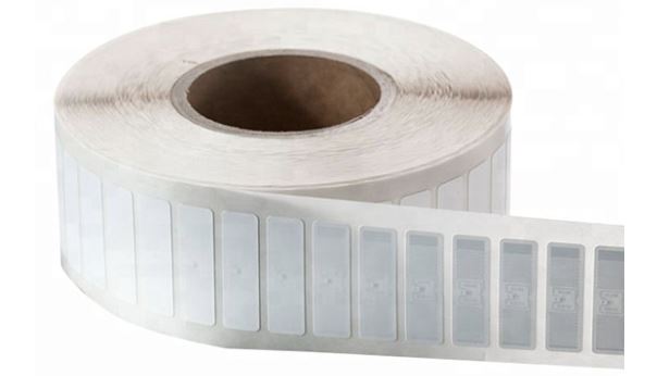
Lot management revolves around the concept of a known quantity of deliverables from a specific process step. In the realm of RFID label production, a lot typically corresponds to one roll of labels.
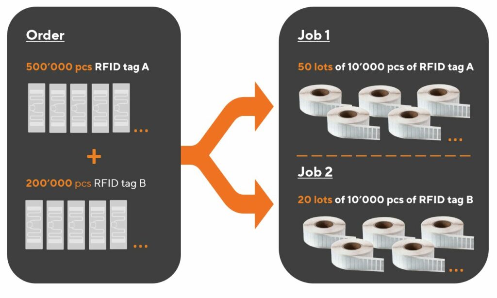
A closely related term is “job.” A job refers to an operation dedicated to producing a specific type of product for a customer or an internal order. Importantly, the process and output remain consistent throughout a job, which may encompass one or multiple lots.
The terminology is easiest to explain with some pictures.
Relation of a lot to an order from a customer, and a job in production.A lot is typically the same as a roll.
Before starting a job in the Tagsurance GUI, it is possible to define the lot. The lot definition includes details such as.
Are all tags counted, or just the good ones?
Is counting across lanes, or on a single lane?
Is the lot change marked with a cut mark?
What should the machine do when the lot is complete?
Lot management
In a typical production setup, where delivery and production are roll-based, lot management includes:
Producing rolls with the desired quantity of labels,
Understanding the quantity of tags within each roll, and
Generating and reporting relevant data for each lot (each roll)
Tagsurance 3 system role in lot management
Tagsurance 3 quality control system plays a pivotal role in the seamless lot management in RFID tag manufacturing. It employs a sophisticated approach to decide whether an individual tag should be counted in the production result set, leveraging comprehensive test data to ascertain the number of tags produced on each lane, differentiating between good and failed tags.
One of the distinctive features of the Tagsurance 3 quality control system is its granular understanding of the location of each tag on the production line. It precisely tracks the lane and the distance from a trigger sensor in millimeters, providing essential position information. This combination of counts and position data serves as the cornerstone for effective lot management.
Given that the Tagsurance 3 quality control system possesses a wealth of information, it becomes the logical and secure choice to entrust with lot management. An alternative approach could involve transmitting count and fail status information to other machine components, such as the machine PLC. However, this introduces unnecessary complexity and potential risks. In high-speed production lines, even a minimal delay in data transmission (from Tagsurance 3 to machine PLC) carries the risk of misaligning counts by a single tag.
The optimal and most efficient solution is allowing the Tagsurance 3 quality control system to take charge of lot management for the following reasons:
Precise Quantity Tracking:Tagsurance 3 is equipped to accurately determine the number of tags in a roll.
Comprehensive Reporting:Tagsurance 3 generates and reports relevant data for each lot, providing a comprehensive overview of passed or failed tags.
When the Tagsurance 3 system manages the production lot information, the risk of split-brain problems between different systems is eliminated. Additionally, Tagsurance 3 offers the flexibility to provide precisely timed signals before, on, or after lot completion, ensuring a smooth and synchronized production process. This level of integration not only enhances operational efficiency but also mitigates the potential risks associated with data transmission delays in a fast-paced manufacturing environment.
Cut mark
The cut mark serves as a practical tool in lot management, providing a visual demarcation between the end of one lot and the commencement of the next.
Cut marks indicated in Tagsurance 3.
Tagsurance 3 system seamlessly integrates with the manufacturing process, triggering the device responsible for creating cut marks. In many instances, the same device used for marking failed tags is employed for printing cut marks as well.
What does the machine need to handle?
While the Tagsurance 3 system handles various aspects of lot management, the tag manufacturing machine still plays a critical role, particularly in the precise execution of cutting tasks to create the desired rolls.
There are different ways to do this:
Automatic turret rewinders
Some machines incorporate automatic turret rewinders, presenting an efficient solution. In this setup, the production job operates continuously, and rolls are automatically cut to the correct size. This automation eliminates the need for manual roll changes by operators.
Cut mark and manual cutting
In certain scenarios, manual or semi-manual cutting methods prove to be a better alternative. Safety considerations often drive this choice, as automatic cutters need to be well-shielded for the safety ofrom human operators.
In a manual or semi-manual process, the machine halts when the liner reaches the cut position, such as at a splicing table. The operator then manually cuts the liner before seamlessly continuing the process with a new output roll.
This video shows an example of a Turret Rewinder by GM where, at the end of a lot, the machine first slows down and stops, and then an operator cuts the web and finally restarts the machine.
Selecting the appropriate cutting method depends on factors such as safety requirements and the layout of the roll handling area. Whether through automated turret rewinders or manual cutting processes, the tag manufacturing machine’s role in achieving precision and efficiency ensures the delivery of high-quality RFID tags.
Must-have machine features for seamless integration
One indispensable feature that facilitates the seamless integration of lot management with automated testing solutions is a digital IO (Input/Output) input, acting as a control mechanism for the manufacturing machine.
Stop signal input
For efficient lot management, there is a need for precise and controlled stopping mechanisms. Particularly in high-speed machines, abruptly halting operations may compromise accuracy, leading to challenges such as incorrect cutting positions on automatic turret rewinders or misalignment at the splicing table. The inclusion of a digital IO input allows for a controlled cessation of the machine, ensuring accuracy and reliability in the manufacturing process.
Slow down signal input
In practical terms, high-speed machines benefit from a gradual slowing down process before coming to a complete stop. This gradual deceleration is vital for intricate operations, such as ensuring precise cutting positions or accurate alignment at various stages of production. The machine’s ability to receive a digital IO input for initiating the slowdown process enhances the overall control and precision of the manufacturing workflow.
The machine slows down before stopping.
Serial port interface alternative for stop and slow down signals
While digital IO inputs serve as the standard for most machines, it’s worth noting exceptions, such as the utilization of a serial port interface in certain models like the Muhlbauer DDA machines. However, in general, the industry standard leans towards the effectiveness of digital IO inputs for optimal control and coordination between lot management and quality control systems.
Nice-to-have machine features for improved efficiency
Two features that significantly contribute to this efficiency are Cut Mark Capability and Operator Signal Integration.
Cut mark capability
Having a discernible cut mark on labels proves invaluable for human operators, especially when machine stopping accuracy is not within a few millimeters. This visual indicator aids operators in clearly identifying which labels belong to the previous lot and which are part of the next one. Even with automatic turret rewinders, the presence of a cut mark provides operators with peace of mind regarding the correctness of quantities.
The Tagsurance 3 system excels in this aspect, precisely triggering the cut mark at the right position. This feature not only enhances accuracy but also empowers operators with a clear demarcation between lots, ensuring seamless continuity in the production process.
Operator signal
Efficient lot management extends beyond just machine capabilities; it involves effective communication with operators. Even in the case of automatic turret rewinders or manual cutting scenarios, alerting operators when a lot is nearing completion proves invaluable. This proactive approach allows operators to prepare for tasks such as cutting the liner and changing the roll promptly, minimizing machine downtime.
The Tagsurance 3 system takes the lead by providing timely signals, either on lot completion or even a predetermined quantity before completion (e.g., 500 labels before the lot concludes). These signals can be utilized by the machine to trigger visual alerts, such as signal lights, or audible notifications through loudspeakers. This integrated communication ensures that operators are well-informed and can take prompt action, contributing to a more streamlined and efficient RFID tag manufacturing process.
Signal lights alert the machine operator.
Strategic considerations for a label manufacturer to optimize lot management
The seemingly minor features within the production machinery play a pivotal role in the seamless execution of lot management. Features such as
slow down signal input,
stop signal input,
serial port interface on some Muhlbauer DDA machines,
ability to print cut marks and,
ability to signal the operator
might appear subtle, but their absence can pose challenges in implementing effective lot management.
When investing in a new label manufacturing machine, ensure that lot management-related details are explicitly specified. The absence of connectors and signaling means can prevent lot management from working optimally. As RFID technology evolves, these features become indispensable for RFID production and quality managers seeking to elevate standards and achieve greater efficiency in the tag manufacturing process.
Connect with us to learn more about Tagsurance 3 lot management features and integration into production machines.
Our past two Voyantic webinars have focused on educating the label-converting industry on RFID – how to get started with RFID labels and what are the key things you should consider to succeed in the RFID business.
The first webinar covered the RFID technology basics for label converters. (If you missed it, you can watch the recording here).
For the second webinar, we invited panelists from different companies in the RFID label ecosystem, including an inlay supplier, a converting machine manufacturer, and a label converter, to give their perspectives on what is essential in RFID label converting. We also had our own expert on the panel to talk about the importance of quality inspection in RFID label production.
Check out the webinar recording or read the highlights from the webinar discussion below.
Wayne Oldham, Innovation and Sustainable Technology Director at 4id Solutions. 4id Solutions is a label convertercompany specializing in RFID.
Axel Hess, Product Manager RFID at BW Papersystems. BW Papersystems is a converting machine manufacturer and a pioneer in RFID technology.
Amy Lu, Global Sales Manager at Arizon RFID Technology. Arizon is anRFID inlay and tag manufacturer, providing ODM & OEM services to RFID companies and system integrators.
Gerald Smid, Solution Specialist at Voyantic. At Voyantic, Gerald helps our customers integrate and set up Voyantic’s quality control systems on their RFID production machines.
Understanding the RFID Label Buyer Needs
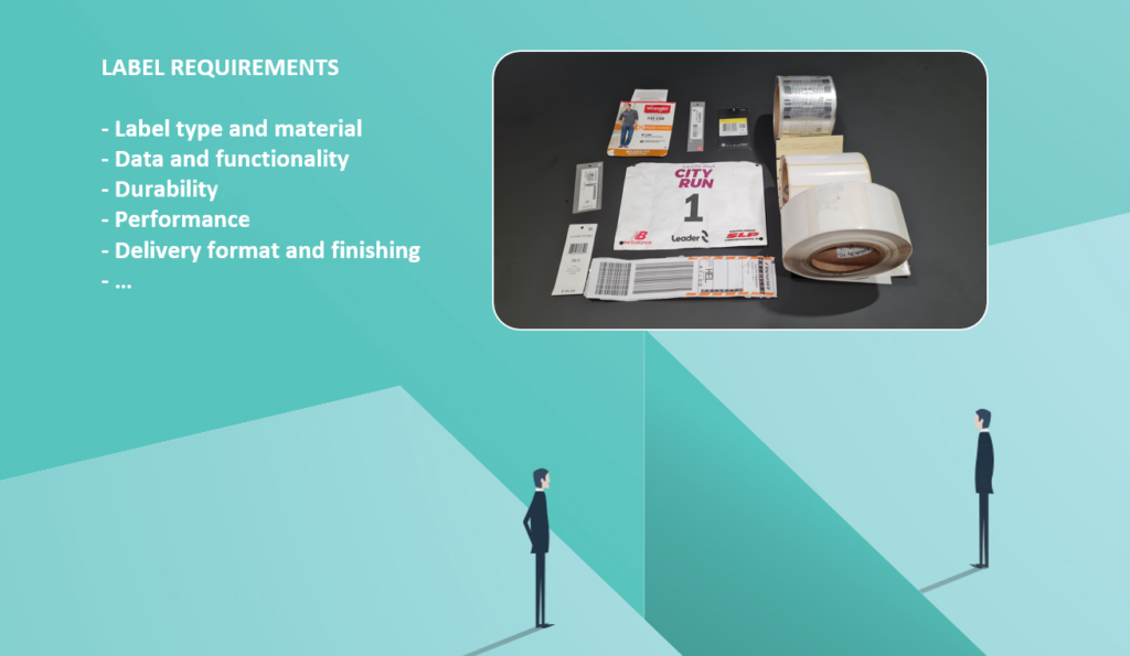
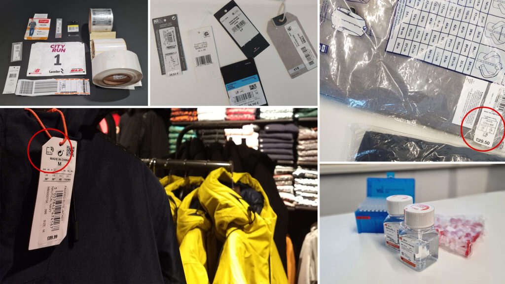
When it comes to RFID labels, there is often a gap between a customer’s request and what the customer needs – the initial customer request often differs significantly from the final product they end up getting. When customers have a weak understanding of RFID technology some level of education is always required. Education is needed to make sure the label buyers understand the capabilities and limitations of the technology and to ensure they have a clear understanding of their use case requirements in order to find the right label product.
To address this challenge, companies like 4id Solutions employ a range of templates with specific questions that help in identifying the customer’s exact requirements. The questions range from technical aspects such as what frequency they need, features, performance, and data requirements to material selection, use cases, and form factor requirements. Voyantic has also put together an RFID Tag Buyer’s Guide with a checklist for label requirements and considerations.
For both label converters and end customers, understanding the application is also critical in the RFID inlay selection process. Some products may be challenging from an RF perspective, for example, products containing metals or liquids. These kinds of products require an inlay designed specifically for those purposes. The number of RFID labels that need to be read simultaneously also varies according to the application. In some use cases, like apparel inventory, where multiple labels must be read simultaneously, the choice of inlay becomes crucial to ensure stable and consistent performance. Inlays are always designed, and often certified, for specific applications and materials. New customers require guidance to select the right inlay for their application.
Label type and functionalities are selected based on the application and the product type.
From an RFID converting machine manufacturer’s point of view, the customers’ challenges include narrowing down the focus of their RFID project. Customers must not only consider the shape and size of the RFID label but also the choice of materials, inlays (dry or wet), and chip direction. These choices significantly affect the configuration of the converting machine. The clearer the output specifications are the better the machine can be configured for a specific product.
Whether we are talking about machines, inlays, or ready labels, standardization, and shared practices within the industry could further help the industry with interoperability and drive the adoption of the technology.
Best practices:
Ask a lot of questions from your customers to nail down requirements
The required read range and the reader type are factors in inlay selection.
RFID Label Converting Practicalities
The biggest difference between RFID label converting and traditional label converting is that RFID labels contain electronic components that can be easily damaged in the converting process. The most effective way to avoid any issues is to understand your converting equipment, have a strong relationship with your suppliers, and ask as many questions as you can possibly think of. No question is considered too trivial in the RFID field, as asking the right questions can potentially save thousands of dollars that would be lost in a failed production run.
For a label converter, it is also important to have a good relationship with your inlay supplier to make sure you have all the latest information and understanding of the inlay materials and the impact they will have on how the materials run through your converting press. It is always better to do test runs with new materials and construction to see the impact on the converting process.
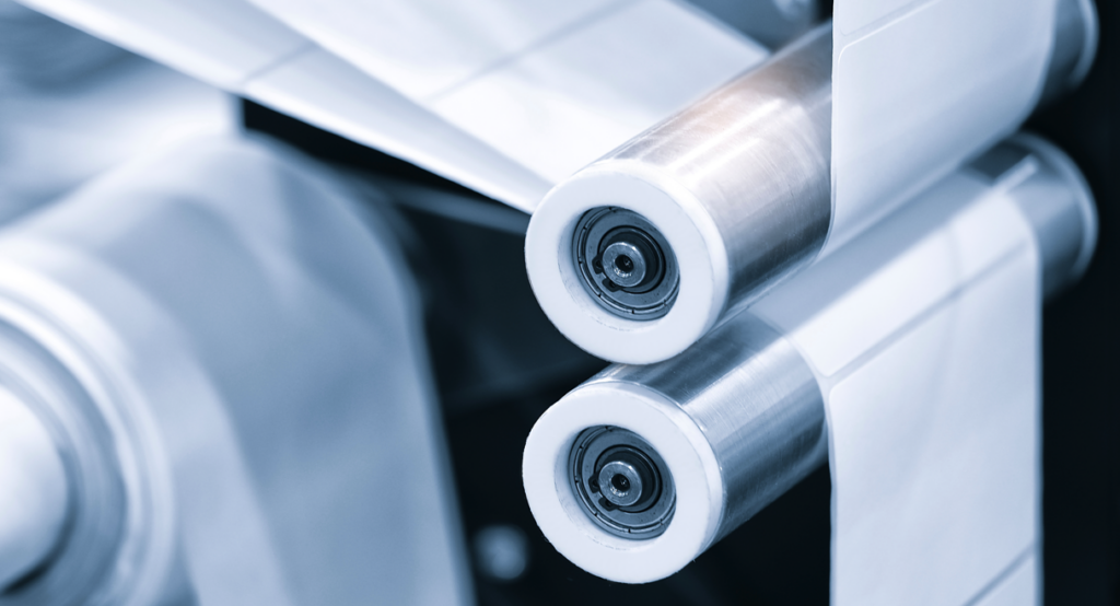
Protecting the IC within the RFID label is imperative to prevent mechanical damage. Traditional label manufacturers may focus on production speed and appearance, while RFID label converters need to prioritize IC protection. To protect against damaging the IC, there are special rollers available with IC protection (avoidance slot) or you can use special rollers with very soft materials to protect the IC from pressure.
Maker sure the machine rollers are suitable for RFID labels.
Another important aspect to consider is ESD (electrostatic discharge) protection. ESD control systems are vital, especially when exposed antennas are involved, ESD can potentially damage the tag IC.
Best practices:
Ask a lot of questions from your machine and inlay vendors
Know your machine!
Do test runs
Consider IC protection in every production step
Consider ESD protection
The Importance of Quality Inspection
“It’s very hard to damage a piece of paper, it’s very easy to damage an [RFID] inlay when you are running it through a converting press. And it’s very easy to damage a lot of inlays very quickly when you don’t have the right processes in place.” – Wayne Oldham, 4id Solutions
For a label converter who cares about the quality of the delivered products, a proper RFID quality control system is essential. Without RFID inspection, there is no way to guarantee the quality of the labels that have been sent to the customer as RF performance cannot be visually verified. A damaged RFID label may look exactly the same as a working one. RFID label performance can only be verified with RF measurements.
A professional RFID quality testing system provides a comprehensive assessment of the tag’s performance on multiple frequencies. Using a simple reader to test that the tag responds, does not give a full picture of the performance nor assurance that the tag will also work in the end user application, from the required distance and attached to the product. A testing system is also a valuable tool for the machine operator, giving visibility into the production process to ensure everything runs smoothly.
A quality control system gives a full picture of the RFID labels’ performance and detects labels that are outside of specifications.
Each label must be tested individually, at high production speeds, and faulty tags can be marked, removed, or killed using chip killers or chip crunchers, depending on customer preferences. What is done to the faulty tags post-production is another important consideration for the label converter. The types of machines and processes handling bad labels also depend on the label types, for example, whether you are producing single tickets vs continuous label rolls. Some customers choose to save costs and remove the faulty, marked labels themselves in the label application process.
Best Practices:
Test every label in the production line with a proper RF inspection system
Long-Term Considerations for RFID Label Converters
The RFID market is growing, and long-term considerations are integral when purchasing RFID converting machines. Companies must consider their target markets, future requirements, and budget when making decisions on investments. The choice of machine impacts the types and volumes of labels that can be produced.
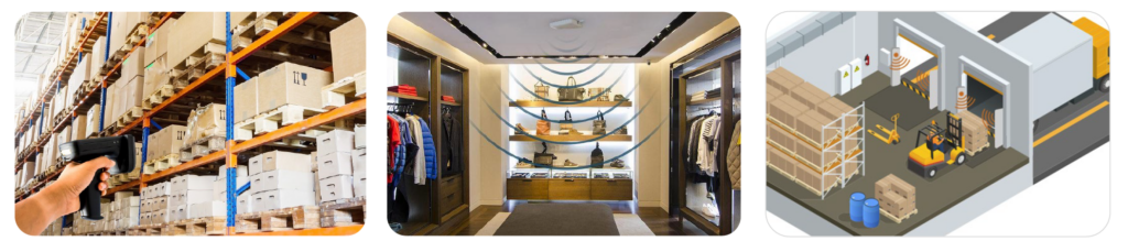
Although retail is still driving the market, several applications, such as consumer packaged goods (CPG), healthcare, and logistics, hold promise in the RFID industry. To stay informed about market trends, consult reports from the RAIN Alliance website. The RAIN Alliance also serves as a valuable resource for networking with industry experts and peers.
How to Get Started with RFID?
For those new to RFID converting, education, building in-house expertise, and early engagement with suppliers are crucial. Take the time to understand the technology, machines, and various aspects involved. Navigating the world of RFID label converting is a process that demands a deep understanding of customer needs, best practices, long-term considerations, and the broader RFID ecosystem. You also need to be agile — the RFID industry develops quickly, and new tag ICs with new features and functionalities are constantly introduced. However, the RFID industry also offers numerous opportunities for new converters as well as customers.