All blog posts

Vehicle RFID Tags – Big Benefits with Some Challenges

Nov 30, 2016

中文版 Chinese version

Electronic Vehicle Identification (EVI) is a perfect match for RAIN RFID (UHF RFID) technology. Once a vehicle is tagged, the possibility to identify the vehicle remotely enables a lot of applications and services. While vehicle tagging is of high interest, it is not the easiest task. In the past few months I have worked with some vehicle tagging projects and learned that the application requires some special attention from technology providers.

EVI Tag Types

The EVI tags come in different forms. Most common EVI tag types are

  • windshield tags attached to the windshield inside the car; and
  • license plate tags mounted on license plates outside the vehicle.

There are some specific design issues related to both of these tag types.

License plate tags must be on-metal tags, and very durable. They must survive weather conditions and car washing. Also, the position and the mounting angle are rarely ideal for readers. The natural best reading direction is straight backward (or forward), and at low height. In many applications the goal is to identify a vehicle approaching an identification point, for example an access gate or a road toll collection point. Reading would preferably be done from above or from side with an angle.

Windshield tags provide better reading angle. The challenge is to design a tag that works well with all possible windshields, regardless of the windshield’s angle, thickness, material, embedded technologies and type and proximity of the windshield frame to the tag position.

Both passive and semi-passive tags are commonly used. The semi-passive tags are battery powered; more of those can be read in earlier Voyantic Blog post.

EVI Tag Applications

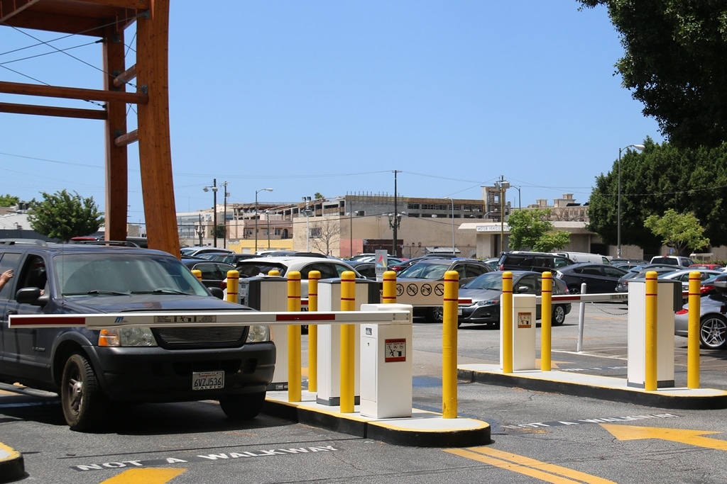
Once the tagging is successful, it is easy to find use for the tags. Applications include road toll collection, tracking vehicle registrations and inspections, tracking tax payments, and parking control. Many of the applications are initially set for government purposes. Once the tags are in place, they can also be used in various value added applications of the private sector. Even if the tag is initially placed for registration, it can be used as a parking permit and gate access permit of a housing community.
Performance Testing of EVI Tags

A car is a special case of a tagged item. There are components that reflect RFID signals, absorb or block the signals, and may even resonate with RFID frequencies. These effects are different to different reading angles, they vary when a tag is attached to different position in a vehicle, and may even change when a tag’s mounting orientation changes. At Voyantic we have assisted several companies in defining test methods and processes for optimizing the EVI tag performance.

With the Voyantic Tagformance Pro system it is possible to test the sensitivity, tuning and backscatter signal strength of the car tag. The Tagformance system is an essential tool for evaluating effects of reading angles and mounting positions. The system can also be used for optimizing the EVI tag performance, finding optimal tag positions in the cars, and for finding optimal reader antenna positions for the applications.
Learn How to Test EVI Tags with Tagformance Pro

Download our application note to learn how to avoid the pitfalls of EVI tag testing!

All blog posts
All blog posts

Designing a RAIN RFID Sensor. Simple, or Is It?

Mar 23, 2016

中文版 Chinese version

Combine identification, sensors, low cost and years of life time together and you certainly end up with a disruptive mixture that is set to boil over in the near future. RAIN RFID sensors may not be a huge market just yet, but we can see many companies putting a lot of development effort on them. Read on to see an introduction to the six topologies that I’ve seen utilized so far.

1) Affecting Antenna to Chip Matching

Right from the beginning of the UHF RFID, engineers have been aware of the inlay antenna’s sensitive nature to change its parameters whenever just about anything changes in its proximity. So, it didn’t take long for scientists to call it a sensor. No added energy was wasted on sensing electronics, therefore potentially long sensing ranges were expected. In practice, however, these type of sensors never got too much of a foothold on the market, as the tags were still sensitive to many measurable parameters, and not just one.

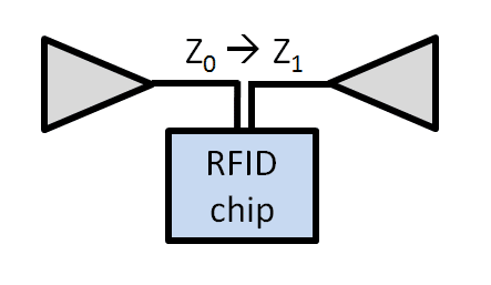
The impedance of the antenna is affected, making a detectable change in frequency tuning, activation power, or RSSI.

2) The Dual Tag Relative Approach

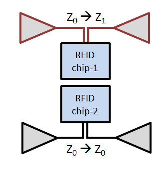
To address the real world problems of the previous approach, a simple improvement was soon used. This time, two similar inlays were encapsulated into one physical tag casing, but one of the antennas is made more sensitive to one particular property. For example, if salt impregnated foam is placed over one of the inlay antennas, it doesn’t affect the antenna when dry. However, when humidity rises, it will deteriorate the performance of this antenna at a much faster rate. The reader would poll both of these tags, typically of a sequential EPC code, and monitor the difference between the two RSSI levels.

The impedance of one of the antennas is made much more sensitive to the parameter to be measured.

3) The Embedded Tag

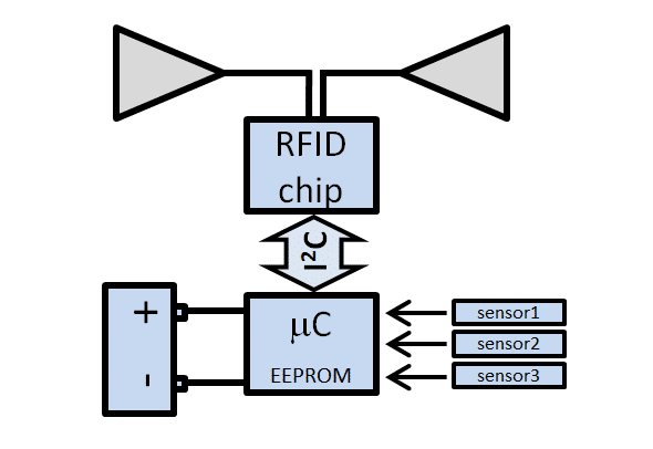
A few years ago the most common type of sensor tag was the embedded type of tag. In this form one or several sensors and inputs can be monitored, logged into memory and read from there when needed. Practically any type of sensoring can be performed in this way, but the solution requires a battery. Although the battery does not sound like a too bad thing to have inside, however the advantage to other technologies, like Bluetooth LE, is rapidly lost. There are also several RFID chips that work with the same principle, but alone without a separate microcontroller.

The RAIN tag uses an I2C interface to interact with a separate sensing circuitry. All this requires more power that the tag can harvest from the RF field, thus a battery is added.

4) Using Automatic Chip Impedance Tuning

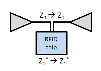
Adaptive chip impedance tuning was long awaited, and finally RF Micron was among the first to arrive to the market with a chip with that capability built-in. It didn’t take long till it was used to detect changes in the antennas proximity just like in the case 1. The biggest difference is that now the sensing result can simply be read from the tag memory and not from the RF properties of the tag.

An RAIN RFID IC with automatic chip impedance tuning capability stores the data in the tag memory where it can simply be read with a reader.

5) Binary Sensing

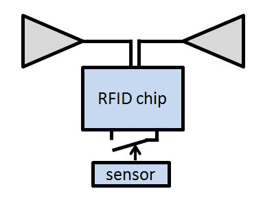
Several ICs have a special pin called the tamper detection pin. Whether this pin is in contact with ground or not can be polled by the reader. It is thus not so difficult to turn this tamper function into a sensor with a bimetallic strip, mercury switch, level float, magnetic switch, NTC resistor, etc. The fact remains that this topology of sensor remains binary.

ICs with tamper detection can be turned into a binary sensor with relative ease.

6) Inbuilt Sensing Capability

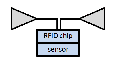
To bring potential cost down and optimize the energy consumption of the tag, the sensor is best integrated into the RFID IC itself. As no busses, microcontrollers, sensors, etc. need to be powered externally, the reading range can be potentially close to that of industry standard tags. The range of measured properties are more limited with this approach, temperature being the simplest candidate.

Built-in sensors can be powered from the RF field without a battery.

All this is to say that RFID sensoring can, in fact, be really simple. However, to get the solution working right also on-site with a known level of sensing accuracy requires advanced methods and a correct set of tools.

Getting It Right With Proper Tools

A number of RFID sensor developers are already using diverse functionalities in the Voyantic Tagformance systemto accelerate tag development cycles, optimize designs and to characterize their products. The more data there is in the sensor tag datasheet, the easier it is for anyone to take it into use!

If there is a particular type of testing you need to get done, but cannot find that particular function in our software GUI, please do not hesitate to contact us! Check out also our earlier blog post of passive RFID sensing!


Learn How to Design Passive Sensor Tags

Download our application note “Utilizing Voyantic Tagformance to Speed Up Development of UHF RAIN RFID Sensor Tags” to learn how to design passive sensor tags!

All blog posts
All blog posts

This Doesn’t Look Right – Should I Contact Technical Support?

Dec 11, 2015

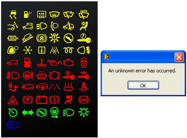
What do you do if, one morning, a new light with some strange symbol is suddenly lit on your car’s dashboard? You probably pull over and start browsing the car owner manual. You may be a little worried. Did I do something wrong? Can I fix this myself, or does the car need to be serviced? How long will I need to survive without my car?
In the same way, your Tagformance, the RFID test system that you typically use every day may have a problem you need to solve. You may already be an experienced user, or maybe you have just recently started to work with the system. When a new error message pops up or you get unexpected measurement results, it’s just like with your car. What’s wrong? Should I contact Voyantic Technical Support?

The answer to the last question is yes. You should.

*‘No such thing as a stupid question’ is a common phrase with a long history, and it makes perfect sense to me. *

If you have a problem with anything, and there is a possibility to get it solved quickly by asking someone who can help you, why shouldn’t you? The one who asks the “stupid question” may be doing a service to everyone, including the vendor, by pointing out a visible improvement to the product.

Here are some more or less typical situations where you might wonder if you should contact the vendor or just carry on. Uncertainty: You are performing measurements that look nice and smooth, but deep down, you are still wondering whether the results are correct? Is there some bias in the device? Am I measuring the right way? By contacting Voyantic Technical Support, we can verify if the device is OK by comparing the reference tag measurement results with the same measurement setup. We can also measure your sample tags and give a second opinion of the results and maybe give pointers on what else you can measure from your tags.

Differences between sites: You may have a colleague in the next room or on the other side of the globe doing the same measurements that you are. The equipment may be the same, the setup may be identical, but still, your results don’t match completely. For example, you get a theoretical read range value of 11 meters, and your colleague measures 10 meters. One meter sounds like a lot, but is it after all? By looking at the measurement data, we can verify whether the difference is something to worry about, or if it fits into production variation and typical measurement accuracy. Other factors, such as temperature, may cause a difference. The effect of temperature is described in more detail in an Application Note, which can be downloaded here. While visiting the site, you may find other Application Notes worth reading too.

Missing features: Different Tagformance measurement options are enabled with the license file. We can create license files where any measurement option can be enabled for a given time. So, if you think that one or more options could be useful for your work, we can enable the option for a trial period. To name a few;

  • Scripter is a great tool to automate your daily measurement routines and reduce the human error from the results.
  • The Tagformance has two Application Programming Interfaces, APIs, that enable you to write your software that uses the Tagformance device. The LabVIEW API is a perfect match for LabVIEW users, and the DLL API serves users of other programming languages.
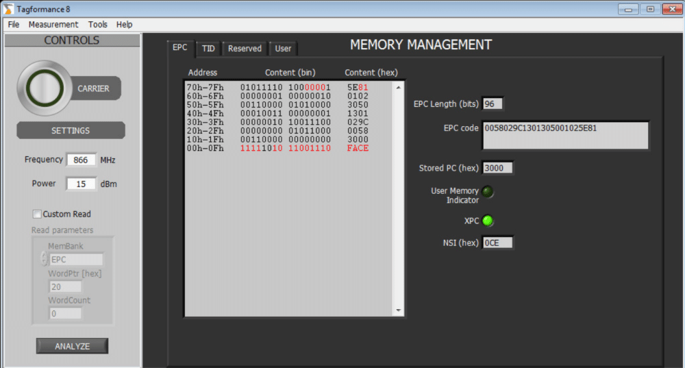
  • Memory management is a brand new tool for one of the hot topics, sensor tags, for example. With Memory management, it is possible to verify changes of any memory address content within seconds.

Memory Management

All this said, do not hesitate to contact us! In most cases, it is a win-win situation where you will get your problem solved or a question answered, and we get valuable feedback, which will help us in making our products even better. We are here to help you – send us a message!

All blog posts
All blog posts

National UHF RFID Standards and RFID Performance

Sep 14, 2015

ISO 18000-63 (6C, EPC Class 1 Gen 2) has been by far the most used UHF RFID standard for several years. There have been some competing standards such as Tagidu, IP-X (tag-talks-only), and ISO18000-62 (6B), but they are nowadays rarely used in new applications. However, new RFID standards still emerge: for example, in Brazil, SINIAV has created a protocol aimed for vehicle tracking applications. In China, a new UHF standard, GB/T29768-2013, has been recently published.

Several tag manufacturers work with these new standards. Why do these national RFID standards exist? And what does it mean for performance testing?

Why Doesn’t Everyone Work with the Same Standard?

Since there is a well-working global standard, it would sound logical to use it for as many applications as possible. But there are some reasons for using something else as well. There may be national interests, or maybe there are special requirements that existing standards don’t cover well enough. For example, ISO 18000-63 was developed for quickly inventorying large quantities of items, and it may not be optimal for reading a single tag that is passing by at 180 km/h. Another challenge may be when the tag is in the windshield of a truck filled with other tagged items.

It should also be noted that the division to separate standards does not always have to be final. Commonly, new functionalities and exclusive features are absorbed into the global standard after they are validated.

What is the Difference Between the Different Standards?

When we talk about passive UHF RFID, we talk about readers that radiate between 860 to 960 MHz to power up remote tags, which in turn modulate their reflection to communicate back to the reader. That is common between all passive UHF RFID standards.

The difference is in how the readers and tags modulate the electromagnetic waves, and what kind of command and response sequences are used in the communication.

One standard might be optimized for quick inventorying while another might provide added security.

Besides, the complexity of the protocol affects the power consumption of the chip and, thus, the read range that can be acquired.

What do the National Standards Mean for Tag Manufacturers

So how should a tag manufacturer respond to a customer’s request to make a tag for a less widely used UHF RFID standard? Well, that depends on the opportunity. But there is nothing to be afraid of in the design process – it is no different from ISO 18000-63 tags. The Voyantic Tagformance system supports performance testing of the GB and SINIAV protocols (as well as older ISO 18000-62 and IP-X protocols).

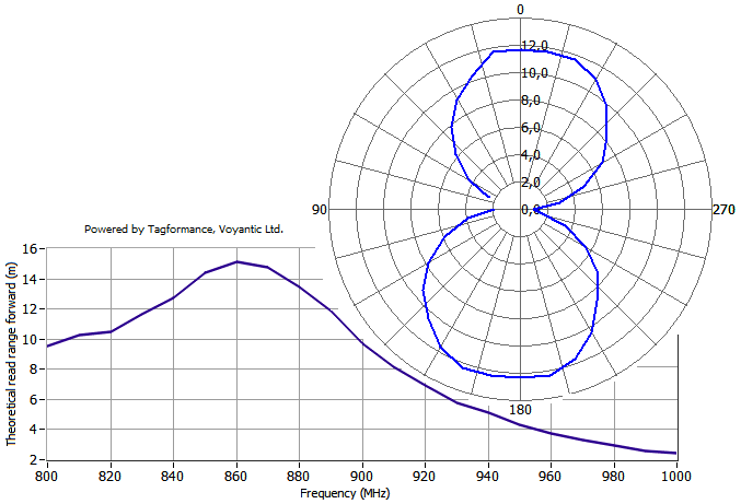
With the Tagformance system, it is quick to characterize a UHF RFID tag regardless of the protocol: just choose which protocol is to be used in testing and then start the selected test. Results include (but are not limited to) information about the tag sensitivity, read range, tuning, and radiation pattern.

Application Developers

New RFID standards are often used in new application areas. With the Voyantic’s Field Engineer’s Kit, RFID tags can be tested within the application – for example, when attached to a vehicle. Vehicles are an example of a quite challenging environment for RFID because of their large metal parts and a variety of different plastic and glass types where tags are mounted. Thus, field test results are crucial.

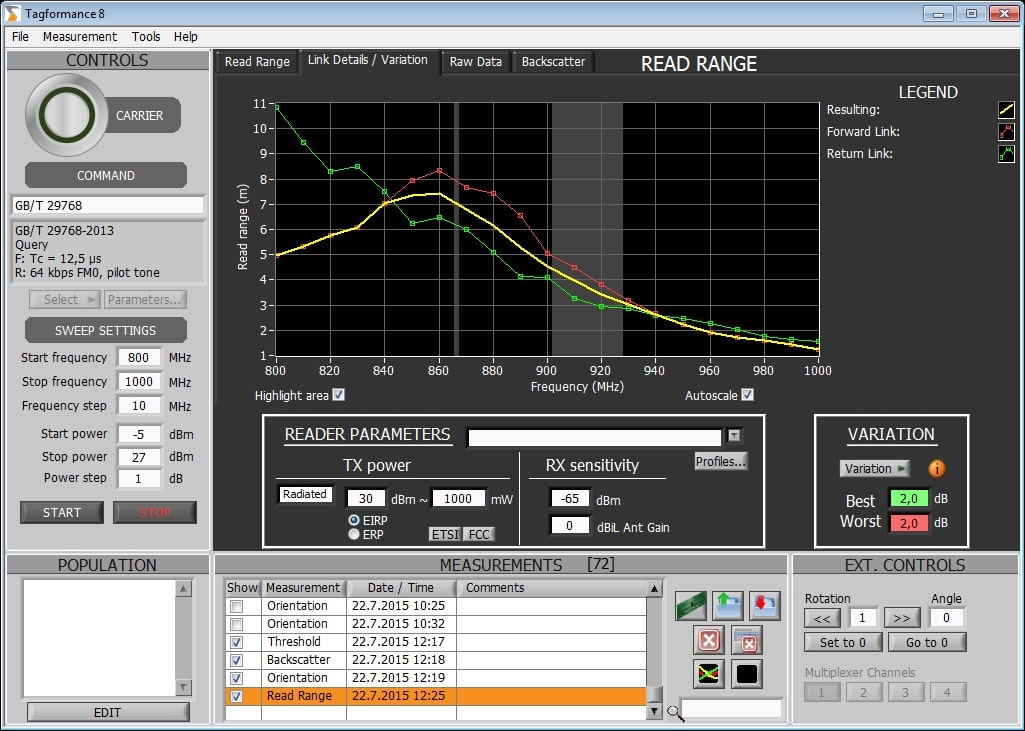
Typical field tests aim to verify the read range. The Tagformance system can be used in evaluating what kind of read range can be achieved with different readers – without actually using the readers. Based on the tag measurements and the reader information input by the reader, the system shows the achievable read range, but also which tag or reader parameter is the bottleneck for system performance.

Download the Tagformance Pro Catalogue

Learn more about the Voyantic Tagformance® Pro Test Device! By combining RAIN RFID and NFC testing into one compact test device, our all-new Tagformance Pro is a true all-in-one tool for anyone either developing or using RFID technology.

All blog posts
All blog posts

How to Improve Efficiency of the R&D Team in UHF Tag Design

Jul 23, 2015

中文版 Chinese version

Being responsible for sales of RFID performance measurement solutions, I’ve had the privilege of meeting with several companies and their design professionals around the world using very different methods for measuring UHF tag performance. Which is the best method then? I’d say it depends on your requirements – for a single essential measurement, you may use various methods, and even a simple technique can be sufficient. However, if you are looking for a way to improve the throughput and efficiency of your R&D team in tag design, the differences in methods are enormous. So, where does the efficiency come from?

The simplest method in UHF tag measurement is using an RFID reader to verify if the tag can be read from a certain distance or not. This pass/fail type of method is easy to do and fast for sure. However, most of the critical characteristics cannot be measured nor verified at all. Another commonly used way based on a set of generic measurement instruments like a signal generator, a network analyzer, and a power meter, is more advanced but unfortunately not anymore fast nor easy to use.

As the two methods introduced above are not ideal in the first place, neither of them can be the real solution to provide increased efficiency either – don’t worry, there is another approach available.

Purpose-built RFID Measurement System

In the R&D environment, most RFID measurements set high requirements for reliability, accuracy, and repeatability of the results and the test method itself. This is the case also in developing new UHF tag designs, thriving to the best possible performance, and at the same time balancing various requirements for different parameters. In this kind of environment the key questions are;

  • How quickly can a set of various measurements be performed?
  • Can the measurements be repeated automatically during the design iterations?
  • What are the possibilities in storing, analyzing, and sharing the results?
  • What kind of competence is required to perform the measurements?

The ideal solution addressing these requirements is a purpose-built RFID measurement system, providing an easy-to-use user interface, high measurement accuracy, compliance with standard RFID protocols, and wideband sweep capability.

How to Enhance the Efficiency of the R&D Team?

Ease-of-Use

There is inherent ease-of-use in the concept of a purpose-built measurement system, as there is only one tester device, including all the necessary accessories and an easy-to-use graphical user interface. A predefined measurement set-up procedure based on a reference tag ensures correct system start and exact measurement results.

Ease of use improves the efficiency of each user regardless of their technical competence. However, the real benefit comes out of the fact that also less experienced persons can easily be trained to perform extensive measurements without having in-depth RF knowledge.

One System – Several Measurements

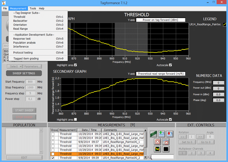
A dedicated RFID measurement system includes all the necessary measurement functions presented in a pull-down menu with suggested default settings for each measurement. Wideband sweep measurement performed over a wide frequency range of e.g., 800 – 1000 MHz enables the flexible visual presentation of the tag detuning phenomenon on different materials compared with on-air results.

Measurement functions menu

One Measurement – Several Results

One single measurement, like the Threshold Sweep, provides several calculated results (e.g., Transmitted power, Backscattered power, Electrical Field Strength, and Theoretical Read Range) that can be viewed simply by selecting the desired result view from the Y-axis pull-down menu.

Results selection menu

Repeatability and Automation

Once the user has selected the function and started the measurement with relevant parameters, the test system provides the results that are stored in the results database with a timestamp and detailed information on all the parameters used in the measurement. Error-prone human interaction and handling of the results are avoided by automated calculation and management of the results.

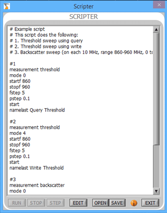
The quality of the measurements can be further ensured by defining and storing a sequence of measurement commands (Scripter) for repeated use. Predefined script together with automatic rotation system eliminates human errors when performing e.g., orientation sensitivity measurements in various positions between 0 and 360 degrees. The example script below defines a sequence of two Threshold measurements and one Backscatter measurement.

Example of a measurement script

Conclusions

A purpose-built RFID measurement system combines high measurement accuracy, versatile measurement capability, and ease-of-use – a unique combination that cannot be achieved with traditional methods.

Accordingly, the improvement of the R&D team efficiency is based on:

  • Quick set-up of the system
  • Better visibility to the performance of the tag under test
  • More measurements in the time available
  • More tests on alternative tag designs in a shorter time
  • Avoiding human errors
  • Testing made it possible for non-RF specialist
  • Shorter time to market for new tag designs.

If you want to learn in detail how the Voyantic Tagformance UHF Measurement System can improve the efficiency of your organization, please download the Tagformance Catalogue below! 

Download the Tagformance Pro Catalogue

Learn more about the Voyantic Tagformance® Pro Test Device! By combining RAIN RFID and NFC testing into one compact test device, our all-new Tagformance Pro is a true all-in-one tool for anyone either developing or using RFID technology.

All blog posts
All blog posts

Why UHF RFID Tag Developers Should Use Wide Band Performance Testing

Jul 10, 2015

中文版 Chinese version

RFID reader frequencies are controlled by governments and limited to narrow frequency bands that vary around the world. When the performance of a UHF tag is evaluated, focusing only on the narrow reader frequency bands is misleading. I have seen in several RFID projects, how the tag performance in field conditions is different from what is expected, leading to delayed projects and expensive re-planning. Testing in a wide frequency band is needed to get the correct information about and good visibility into UHF RFID tag performance.

Detuning as a Challenge

Typical UHF RFID tags operate with a wide frequency band. However, performance still depends on frequency. In UHF RFID tag development, the tags are usually designed to have maximal read range at the reader frequency. This is achieved by tuning the tag to be most efficient at these frequencies.

Succeed in RFID projects with wideband testing

Detuning creates challenges:

When the tags are attached to different materials, their performance at the reader frequency changes.

The entire performance curve shifts on the frequency scale and a change in read range is observed at the UHF RFID reader frequency. This detuning effect is one of the fundamental physical phenomena affecting real-life RFID system performance. If the detuning is not taken into account, the UHF RFID tag’s read range may be only a fraction of what is intended.

In good design, the detuning is anticipated and taken into account. If the tag is intended to be used on a material that causes 50 MHz of detuning, it can be tuned to have optimal free air performance at a frequency 50 MHz higher than the reader frequency. When the tag is on the material, the tuning and performance become optimal.

If the tag is only tested at the reader frequency, it is almost impossible to design the tuning correctly. A wideband view is needed.

Comparing Tag Designs

An example: An RFID user manufactures items made of rubber. The items are delivered on a cardboard package. The user wants to tag the cardboard boxes and wants to have a maximal read range. The items are shipped, and the RFID tags are read globally. What kind of tag would be the best?

Two tag designs were tested using UHF RFID readers with ETSI (865 MHz -868 MHz) and FCC (902 MHz – 928 MHz) frequency bands. In the test, the reader was moved closer to the tag, and the distance was measured when the tag was read the first time. Each test was made twice.

The results show a big difference in read ranges. Tag design A has a 12 m read range on cardboard, but only 5.5 m on rubber. Tag design B has an opposite performance change: 11 meters on rubber and 6.5 to 8.5 meters on cardboard. There is also a difference between repeated measurements, which is significant, especially on the FCC frequencies.

What Really Happens with the UHF RFID Tags?

Because the reader frequency is limited, it is difficult to get a good overview of what is happening when the tag is attached to different materials. The read range is different in various test scenarios, but it is not clear why. Some explaining phenomena immediately pop into the minds of RFID professionals: multipath propagation and detuning. But the results from reader frequencies do not tell how the detuning works.

Which tag would you recommend? Click below to view the wideband test results of the Tags A and B from the Tagformance system or send me an email and let’s talk more! Voyantic offers RFID measurement systems to help tag designers. With precise test results, it is easier to give recommendations with confidence!

Download the test results

All blog posts