I am Sales Director at Voyantic. I have over 15 years of experience from the RFID industry in Europe and the USA. I have two master's degrees: in industrial engineering and in marketing, and two patents in auto-ID technology. I am actively participating in RAIN RFID alliance activities.
Healthcare spending raises steadily as the silver tsunami rolls over societies in East and West. Tightening cost, quality of care and efficiency requirements are some of the drivers that highlight healthcare as one of the strongly growing RFID application areas. RFID improves patient safety, raises operational efficiency and reduces shrinkage.
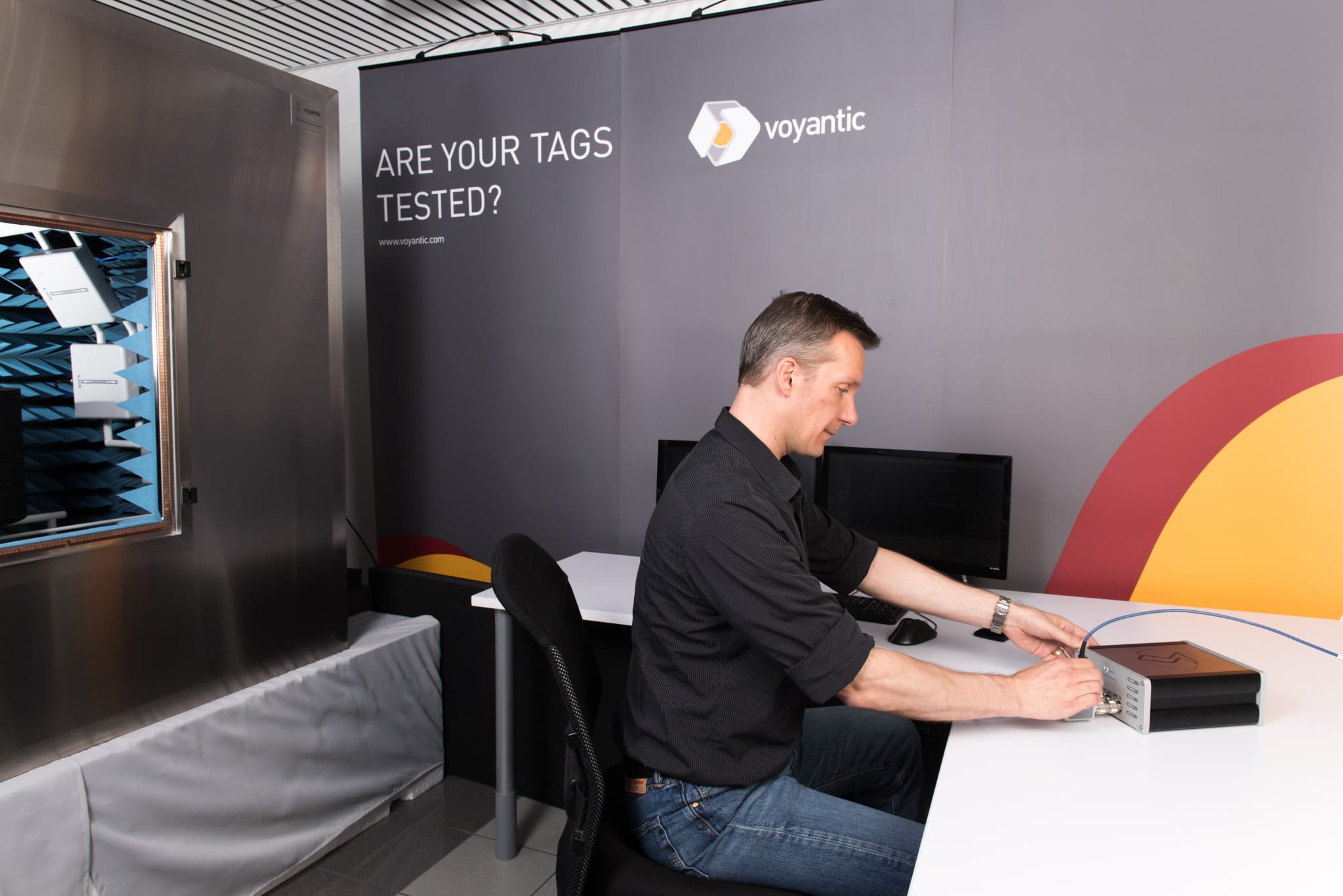
Healthcare organizations have expressed concerns about medical device immunity against RFID, and the RFID technology vendors and regulatory authorities have been quick to respond. A new immunity test standard has been developed in cooperation with RFID and healthcare stakeholders, and released by AIM. This standard has been recognized by FDA and the first test laboratories are already offering Immunity Testing as a service for Medical Device manufacturers.
Interference May Effect Medical Devices
Healthcare organizations are understandably very cautious about any new RF systems that could risk the functionality or reliability of various medical testing and treatment devices. Research projects were commissioned and some studies – for example van Lieshout et al. – found that RFID can induce incidents with medical equipment.
Solution – Standardized RFID Immunity Testing for Medical Devices
To remove possible RFID related risks and uncertainties, RFID industry took action. With the help of industry organization AIM, a new test standard was created: AIM 7351731. This standard describes methods for testing Medical Electric Equipment and System Electromagnetic Immunity against RFID readers.
U.S. Food and Drug Administration FDA soon recognized the standard. FDA has also started to endorse it for medical device manufacturers submitting new equipment to Premarket notification (PMN) process according to section 510(k) of the FDA rules.
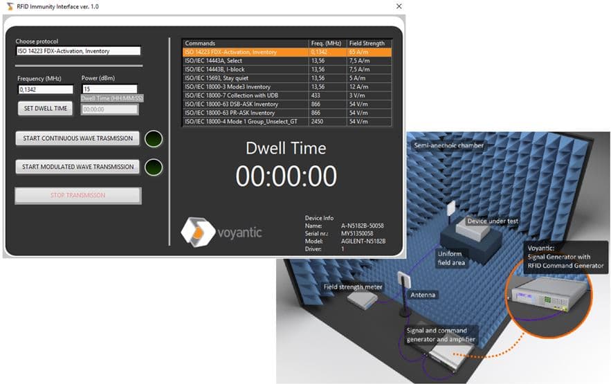
Voyantic was quick to release a solution that conveniently extends EMC laboratories’ existing EMC hardware to support the new AIM standard. Voyantic approach is based on creating the required test commands on a PC software and loading them over Ethernet to vector signal generator (VSG) already in use at the EMC labs. This approach, called Voyantic RFID Immunity Interface, is a quick and cost-efficient way to implement RFID immunity testing, utilizing the facilities and equipment already available.
Do you have any thoughts or questions about the RFID immunity testing? Contact us – I would be happy to discuss this in more detail!
I am Sales Director at Voyantic. I have over 15 years of experience from the RFID industry in Europe and the USA. I have two master's degrees: in industrial engineering and in marketing, and two patents in auto-ID technology. I am actively participating in RAIN RFID alliance activities.
Electronic Vehicle Identification (EVI) is a perfect match for RAIN RFID (UHF RFID) technology. Once a vehicle is tagged, the possibility to identify the vehicle remotely enables a lot of applications and services. While vehicle tagging is of high interest, it is not the easiest task. In the past few months I have worked with some vehicle tagging projects and learned that the application requires some special attention from technology providers.
EVI Tag Types
The EVI tags come in different forms. Most common EVI tag types are
windshield tags attached to the windshield inside the car; and
license plate tags mounted on license plates outside the vehicle.
There are some specific design issues related to both of these tag types.
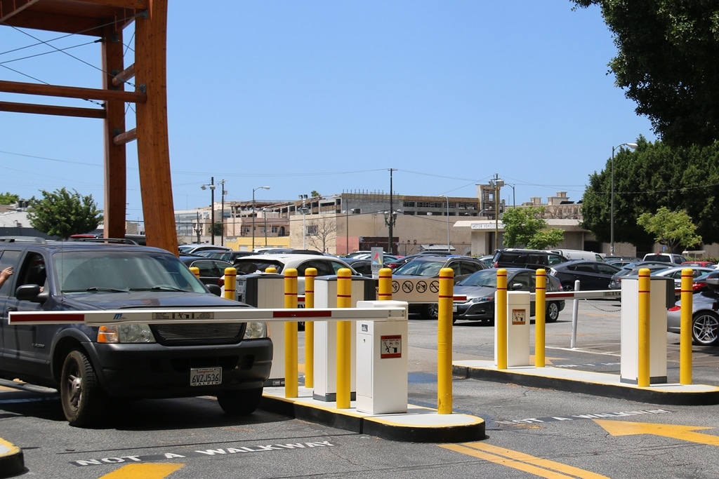
License plate tags must be on-metal tags, and very durable. They must survive weather conditions and car washing. Also, the position and the mounting angle are rarely ideal for readers. The natural best reading direction is straight backward (or forward), and at low height. In many applications the goal is to identify a vehicle approaching an identification point, for example an access gate or a road toll collection point. Reading would preferably be done from above or from side with an angle.
Windshield tags provide better reading angle. The challenge is to design a tag that works well with all possible windshields, regardless of the windshield’s angle, thickness, material, embedded technologies and type and proximity of the windshield frame to the tag position.
Both passive and semi-passive tags are commonly used. The semi-passive tags are battery powered; more of those can be read in earlier Voyantic Blog post.
EVI Tag Applications
Once the tagging is successful, it is easy to find use for the tags. Applications include road toll collection, tracking vehicle registrations and inspections, tracking tax payments, and parking control. Many of the applications are initially set for government purposes. Once the tags are in place, they can also be used in various value added applications of the private sector. Even if the tag is initially placed for registration, it can be used as a parking permit and gate access permit of a housing community.
Performance Testing of EVI Tags
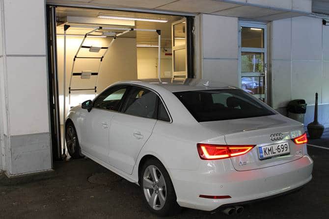
A car is a special case of a tagged item. There are components that reflect RFID signals, absorb or block the signals, and may even resonate with RFID frequencies. These effects are different to different reading angles, they vary when a tag is attached to different position in a vehicle, and may even change when a tag’s mounting orientation changes. At Voyantic we have assisted several companies in defining test methods and processes for optimizing the EVI tag performance.
With the Voyantic Tagformance Pro system it is possible to test the sensitivity, tuning and backscatter signal strength of the car tag. The Tagformance system is an essential tool for evaluating effects of reading angles and mounting positions. The system can also be used for optimizing the EVI tag performance, finding optimal tag positions in the cars, and for finding optimal reader antenna positions for the applications.
Learn How to Test EVI Tags with Tagformance Pro
Download our application note to learn how to avoid the pitfalls of EVI tag testing!
I have been working for Voyantic as a Product Specialist since March 2014 mainly focusing on technical support. Before joining Voyantic I have 15 years' experience in customer support on telecommunications industry.
Creating a tagging solution for passive RAIN RFID tags to a particular application starts with understanding the application specific requirements. That involves plenty of process engineering, but also typically discussions around the expected read range between tagged items and reader antennas. The read range is impacted by several factors and many start the cooking process by looking at the properties of RAIN RFID tags.
Tag datasheets carry plenty of information: protocol, operating frequency, chip type, memory utilization, physical size and much more. Amongst all information on datasheet, I reckon tag dimensions and read range are typically the first ones checked. Both are relatively easy values to understand, although the first one is a fact, and the second more an opinion. In the following I explain how to interpret the tag read range right.
Classic Approach: Take a Tag and Walk Away
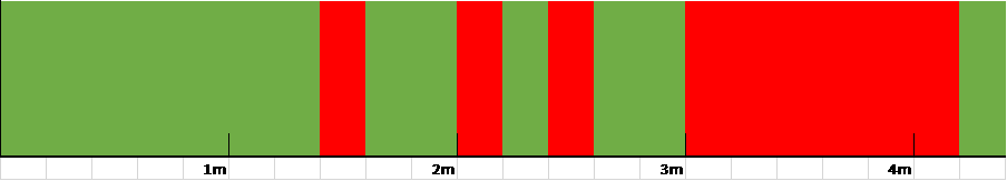
The simplest way to get an idea of the read range is to place a reader to the end of a hall, take a tag and walk away from the reader antenna to see how far the tag can still be successfully read. In this kind of empirical test the result is not a fixed distance under which the reading would always be successful, but instead the result typically varies as below:
Result of a “walk away” read range measurement using a lower end RFID reader. What would you choose for a read range value?
Obviously such a result leaves a problem: how to interpret the results? What in fact is the read range in this case? A bigger problem is that the result is actually a synthesis of so many factors, such as reader properties, tag alignment, other objects in the environment, illumination in the hall, settings in the reader… So, what was it again you wanted to see?
Very few halls, office spaces or basements are stable enough to reproduce the test from day to another with the same test result. Therefore, key delivered value of this approach is merely the physical exercise, and most vendors don’t use these results in their tag datasheets.
Laboratory vs. Real Life Performance
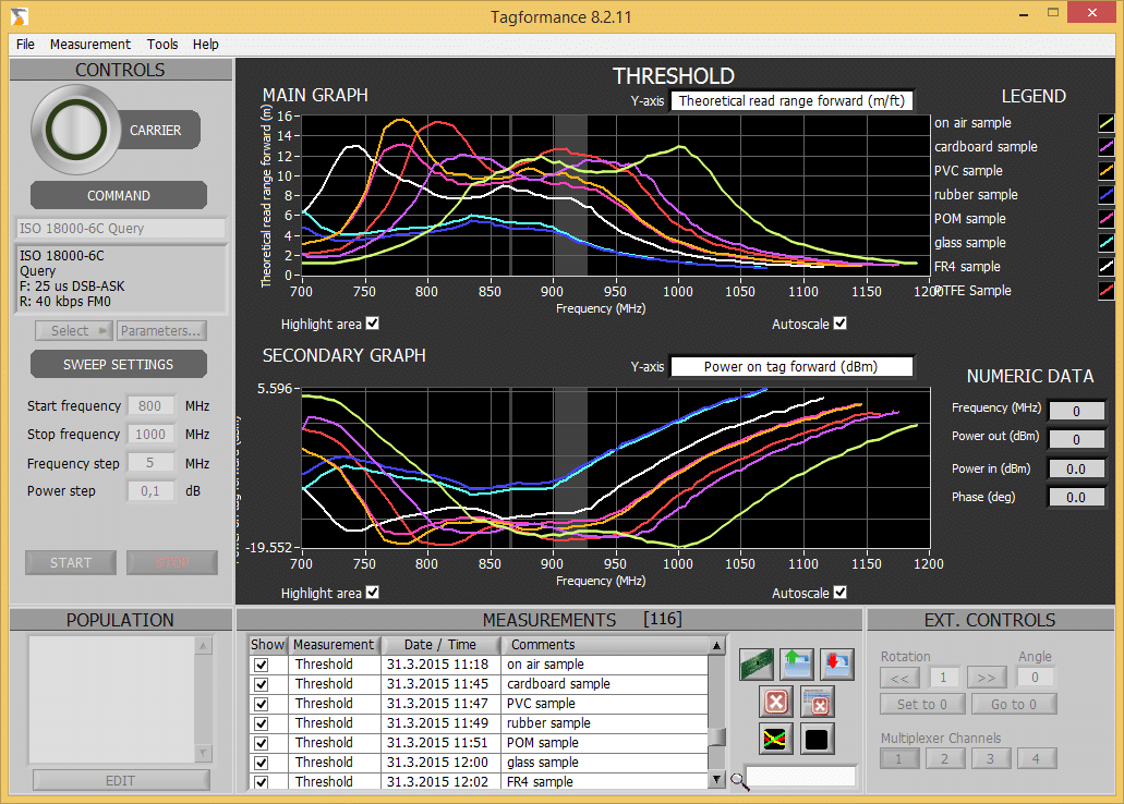
RFID measurement systems characterize tags at high precision after which read range is calculated based on a few assumptions. Laboratory measurements themselves are often performed in shielded and anechoic chambers to remove other variables from the test results, which greatly improves the value of the data and the repeatability of the test process.
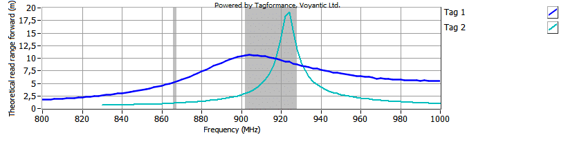
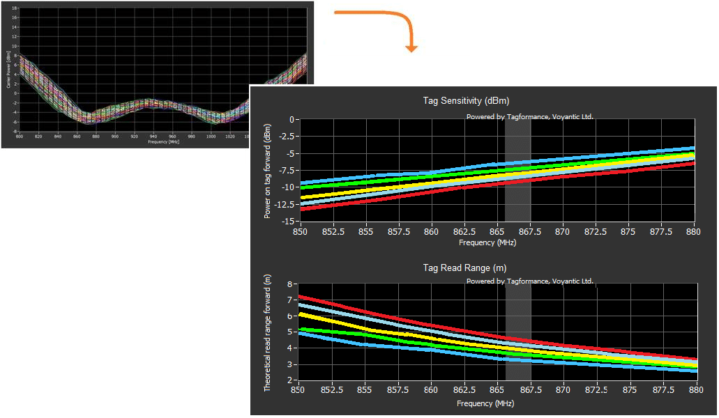
Theoretical read range of two RAIN RFID tags designed for different applications. Tag 2 shows better max read range at the FCC band, but is too highly tuned to efficiently cover the whole band. Despite of its shorter read range, Tag 1 as a broadband design seems like a more reliable choice.
This kind of measurement does not emulate effects of environment where tags are used. Experts talk of multipath propagation and path loss, and some others may talk of reflections, shadowing and interior design. No matter which definition is used, the environment is the grand source of differences between laboratory and real life performance.
Practical Difference of ERP and EIRP
Theoretical read range values plotted by the Tagformance system are based on the Tag Performance Parameters and Test Methods Version 1.1.2, 2008, EPCGlobal Inc. For the read range standard specifies 35dBm EIRP transmit power to be used in the calculation. 35dBm EIRP transmit power equals 33dBm ERP power. 33dBm ERP equals 2W and 35dBm EIRP equals 3.28W. If maximum power 4W EIRP is allowed, as in the FCC band, theoretical read range results can be obtained by adding 11% on the figures shown in the Tagformance software.
Forward Limited Read Range Is Not a Safe Assumption Anymore
As tag dimensions shrink and tag ICs become more sensitive, readers often become the limiting factor of read range. A reader with more sensitive receiver is able to pick up a tag’s reply from greater distance. When read range is analyzed it is typical to separate read range to forward (up) and reverse (down) links.
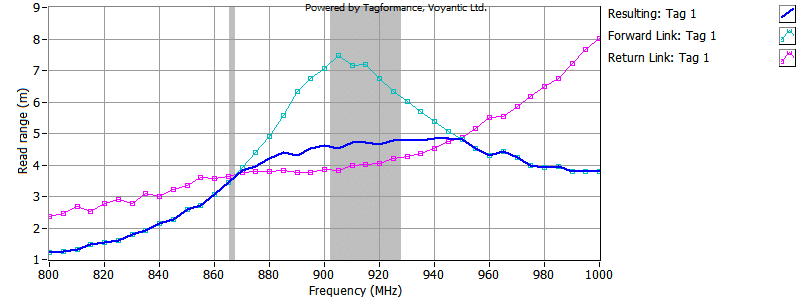
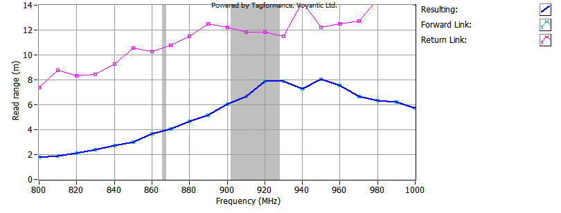
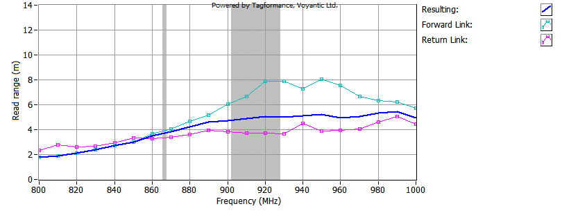
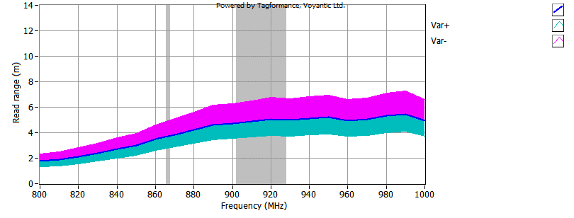
Picture below shows forward and reverse read range curves, which are calculated using 1W ERP transmit power, 2dBi antenna gain and -65dBm receiver sensitivity.
Separated forward, reverse and resulting read range curves. For ETSI range forward and reverse curves are equal, but for FCC range read range is reverse link limited – a reader with more sensitive receiver would improve read range on FCC band.
Tag Close Coupling Issues to Be Addressed by TIPP
As tagging spreads to new product categories in the retail industry, small tagged items are often brought into close proximity to each other. Just think about items boxed for transport. Especially when the distance between tags is less than 3 cm, the tags start to couple with each other.
The close coupling effects will be considered in the upcoming GS1 TIPP global standard. Stay put for Juho Partanen’s upcoming blog post regarding these issues!
From Opinions Back to the Facts
As you saw from the above, the read range is a factor of many issues. As you work yourself through the tag and reader datasheets with the aid of expert tools and good standards, you can connect the dots with relative ease. This process transforms opinions into facts.
I’d appreciate your comments and suggestions around these topics. New perspectives are always welcome.
Learn How to Test the Read Range with Tagformance
Download our application note “Read Range Test with Voyantic Tagformance” to learn how easy it is to test the read range!
Smoos started his RFID business in 2002. Currently, he manages METAG's daily activities to promote RFID measurement and testing solutions in Taiwan. In the meanwhile, Smoos also handles Voyantic business in Asia-Pacific region as APAC Director since 2014.
One of my customers in Taiwan is developing battery-assisted passive (BAP) tags. He called me recently and asked why the read range that they reach with their RFID reader is only a quarter (1/4) of the distance that they measure with their Tagformance RFID measurement system. I answered him with another question: “Do you know your reader receiver sensitivity…?”
What Is a BAP Tag?
A BAP tag has an on-board battery to power its IC, but like a passive tag, it does not have an active transmitter. BAP tags are generally used to reach longer read ranges than what passive tags can provide, or for logging some physical quantity when a reader is not present. As known, the typical limiting factor for the read range of a passive tag is the forward link. In other words, the read range of a normal passive tag is determined by how far the passive tag can be powered or activated, i.e., the tag sensitivity is the limiting factor. Therefore, by default designing the passive tag to receive power from an on-board battery as a BAP tag, read range could be increased.
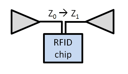
However, since the on-board battery is only used to power-on the RFID IC or to increase the BAP tag sensitivity, the battery does not really increase the tag backscatter power. As a result, the return link will become the limiting factor for the read range of a BAP tag. In order to fully realize the maximum read range of a BAP tag, the reader receiver sensitivity becomes crucial.
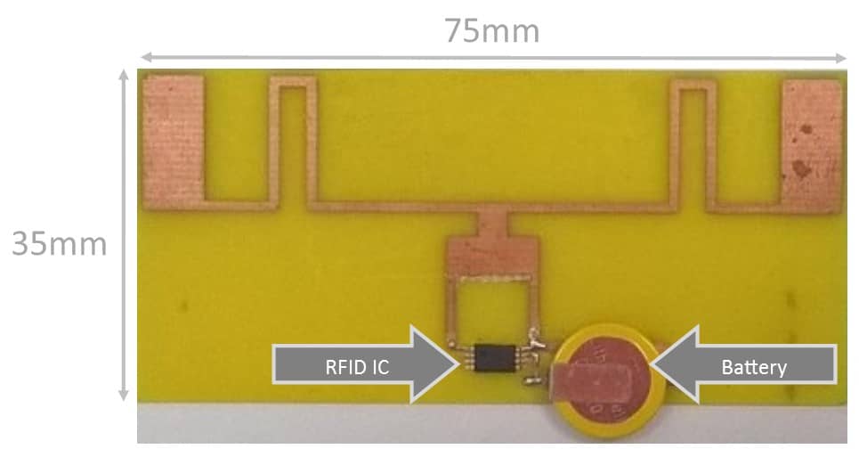
BAP – Battery Assisted Passive – Tag
The Performance of a BAP Tag
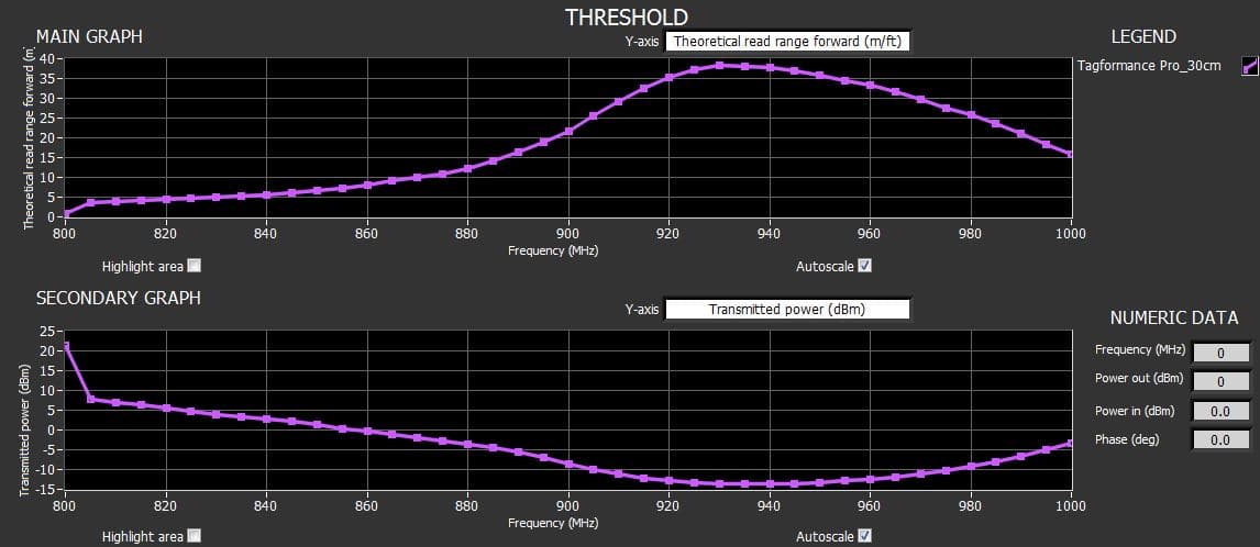
When evaluating the performance of an RFID tag, the starting point is usually measuring the sensitivity of the tag as a function of frequency. The graph below shows the Tagformance Pro’s Threshold Sweep measurement results of one BAP tag. As can be seen, the theoretical read range for this BAP tag is close to 37 meters at 930 MHz. That is a lot; the read range of a good passive tag is around 10 meters.
Sensitivity of a BAP RFID Tag Measured with Tagformance Pro
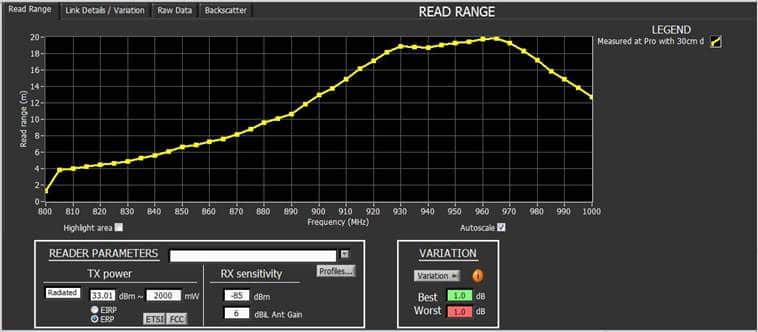
But the forward link read range above is only the theoretical upper limit of the read range that can be reached. Below we use the Tagformance Pro’s Read Range measurement functionality to test the BAP tag with different reader parameter settings. The radiated power is set at 2W ERP. The yellow curve below shows that the read range is about 19 meters at 930 MHz if the reader receiver (RX) sensitivity is -85 dBm.
Read Range of a BAP Tag Measured with Tagformance Pro; 2W ERP & -85 dBm Sensitivity
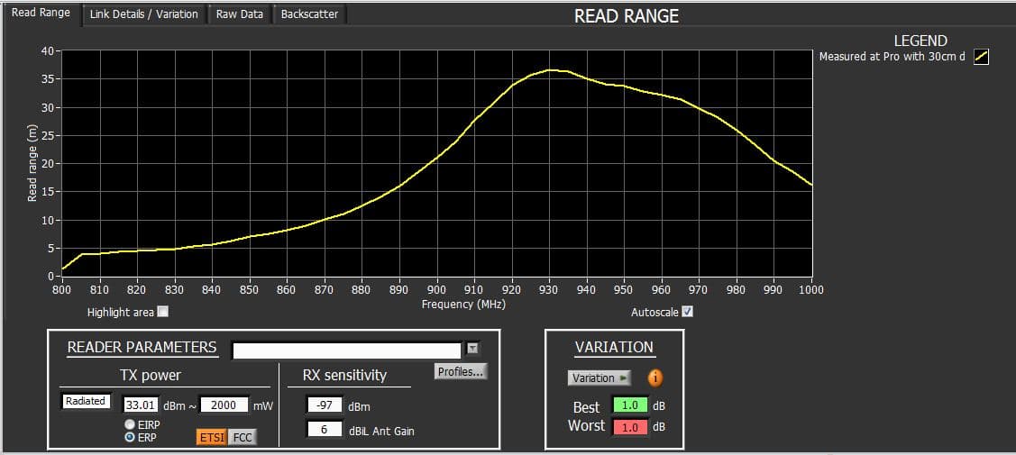
By changing the reader sensitivity in the Tagformance software, we can see what reader sensitivity would be needed to reach the theoretical read range maximum. This situation is shown in the yellow curve below. The reader sensitivity required to reach the 37-meter read range is -97 dBm.
Read Range of a BAP Tag Measured with Tagformance Pro; 2W ERP & -97 dBm Sensitivity
From my experiences, it may not be easy nowadays to find a reader with the RX sensitivity of -97 dBm. Therefore, in order to reach the read range of 37 meters, I have suggested my customer redesign the BAP tag’s antenna to make the tag having stronger backscatter power and use a higher sensitivity reader if possible.
Reader receiver sensitivity is getting more attention in the RFID market after the increase of tag sensitivity both in BAP tags and normal passive tags. This means that the limiting factor for the read range is the return link. Receiver sensitivity is the key to optimizing the read range. Interestingly, most system integrators and even UHF reader suppliers do not know how to measure the receiver sensitivity.
I joined Voyantic during the birth of the RAIN technology and assumed the responsibilities of the CTO in 2009. My MSc level background is in electronics after which I made my PhD in the field of photonics. Currently, I work with new measurement methods, RF design, product prototypes, standards, protocols and IPR.
Combine identification, sensors, low cost and years of life time together and you certainly end up with a disruptive mixture that is set to boil over in the near future. RAIN RFID sensors may not be a huge market just yet, but we can see many companies putting a lot of development effort on them. Read on to see an introduction to the six topologies that I’ve seen utilized so far.
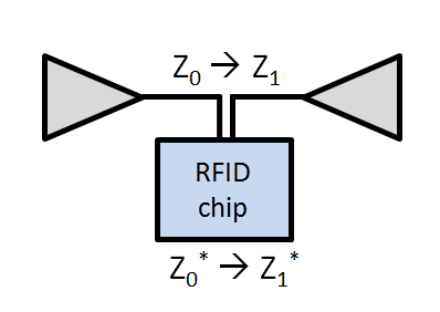
1) Affecting Antenna to Chip Matching
Right from the beginning of the UHF RFID, engineers have been aware of the inlay antenna’s sensitive nature to change its parameters whenever just about anything changes in its proximity. So, it didn’t take long for scientists to call it a sensor. No added energy was wasted on sensing electronics, therefore potentially long sensing ranges were expected. In practice, however, these type of sensors never got too much of a foothold on the market, as the tags were still sensitive to many measurable parameters, and not just one.
The impedance of the antenna is affected, making a detectable change in frequency tuning, activation power, or RSSI.
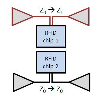
2) The Dual Tag Relative Approach
To address the real world problems of the previous approach, a simple improvement was soon used. This time, two similar inlays were encapsulated into one physical tag casing, but one of the antennas is made more sensitive to one particular property. For example, if salt impregnated foam is placed over one of the inlay antennas, it doesn’t affect the antenna when dry. However, when humidity rises, it will deteriorate the performance of this antenna at a much faster rate. The reader would poll both of these tags, typically of a sequential EPC code, and monitor the difference between the two RSSI levels.
The impedance of one of the antennas is made much more sensitive to the parameter to be measured.
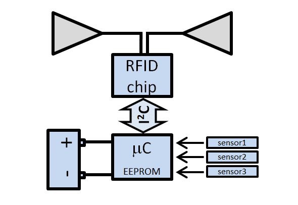
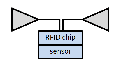
3) The Embedded Tag
A few years ago the most common type of sensor tag was the embedded type of tag. In this form one or several sensors and inputs can be monitored, logged into memory and read from there when needed. Practically any type of sensoring can be performed in this way, but the solution requires a battery. Although the battery does not sound like a too bad thing to have inside, however the advantage to other technologies, like Bluetooth LE, is rapidly lost. There are also several RFID chips that work with the same principle, but alone without a separate microcontroller.
The RAIN tag uses an I2C interface to interact with a separate sensing circuitry. All this requires more power that the tag can harvest from the RF field, thus a battery is added.
4) Using Automatic Chip Impedance Tuning
Adaptive chip impedance tuning was long awaited, and finally RF Micron was among the first to arrive to the market with a chip with that capability built-in. It didn’t take long till it was used to detect changes in the antennas proximity just like in the case 1. The biggest difference is that now the sensing result can simply be read from the tag memory and not from the RF properties of the tag.
An RAIN RFID IC with automatic chip impedance tuning capability stores the data in the tag memory where it can simply be read with a reader.
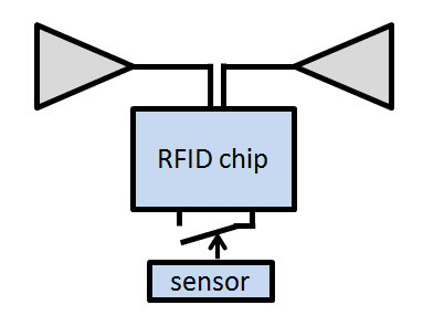
5) Binary Sensing
Several ICs have a special pin called the tamper detection pin. Whether this pin is in contact with ground or not can be polled by the reader. It is thus not so difficult to turn this tamper function into a sensor with a bimetallic strip, mercury switch, level float, magnetic switch, NTC resistor, etc. The fact remains that this topology of sensor remains binary.
ICs with tamper detection can be turned into a binary sensor with relative ease.
6) Inbuilt Sensing Capability
To bring potential cost down and optimize the energy consumption of the tag, the sensor is best integrated into the RFID IC itself. As no busses, microcontrollers, sensors, etc. need to be powered externally, the reading range can be potentially close to that of industry standard tags. The range of measured properties are more limited with this approach, temperature being the simplest candidate.
Built-in sensors can be powered from the RF field without a battery.
All this is to say that RFID sensoring can, in fact, be really simple. However, to get the solution working right also on-site with a known level of sensing accuracy requires advanced methods and a correct set of tools.
Getting It Right With Proper Tools
A number of RFID sensor developers are already using diverse functionalities in the Voyantic Tagformance systemto accelerate tag development cycles, optimize designs and to characterize their products. The more data there is in the sensor tag datasheet, the easier it is for anyone to take it into use!
If there is a particular type of testing you need to get done, but cannot find that particular function in our software GUI, please do not hesitate to contact us! Check out also our earlier blog post of passive RFID sensing!
Learn How to Design Passive Sensor Tags
Download our application note “Utilizing Voyantic Tagformance to Speed Up Development of UHF RAIN RFID Sensor Tags” to learn how to design passive sensor tags!
I am Sales Director at Voyantic. I have over 15 years of experience from the RFID industry in Europe and the USA. I have two master's degrees: in industrial engineering and in marketing, and two patents in auto-ID technology. I am actively participating in RAIN RFID alliance activities.
Content
When selling RAIN RFID tags: wouldn’t it be great to prove that the proposed tag is the best possible one for the customer’s application instead of just sending out loads of free samples hoping that the customer tests them properly? And when purchasing: wouldn’t it be great to have comparable data of how each tag works in your application instead of “our tags are the best ones, you can trust us” statements?
Guess what: it is possible, and in most cases, the salesperson or the buyer just needs to know what to ask. Tag developers have a lot of characterization data ready. Read on to see how to leverage that data following the 3-step approach!
Step 1: Extract Tag Characterization Data from the Production Quality Log
Useful RAIN RFID tag data combines production quality information with detailed laboratory test results. Production quality data is a good starting point since it shows the overall quality variation. With Voyantic’s Sweep Data Analyzer, it is easy to identify the typical and the worst acceptable tag and to quantify variation. Variation can be described, for example, as each tag having a sensitivity of -8 dBm +/-2.5 dB. With the Tagformance viewer software, the sensitivity values can also be translated into read ranges.
RAIN RFID tag quality – variance in RFID production quality
Step 2: Connect RAIN RFID Tag Performance Data to the Use Case
Detailed information about the performance of a RAIN RFID tag can be generated by testing the selected sample tag (typical tag or weakest tag) in a laboratory environment. The goal of the laboratory tests is to show how the tag would perform in different applications. Simply place the tag or tags on Voyantic Reference Materials in different arrangements and run the tests on Tagformance.
When proper test data is available, there is no need for extensive field tests with various tag and reader combinations. Shortening the field tests saves time and money significantly – both for the seller and the buyer.
Typical test results include RAIN RFID read ranges and orientation patterns on various materials and within diverse tag populations. When the tags are attached to different materials, their tuning, and performance level change, with the test results, it is possible to evaluate what the read range would be with varying models of readers. The results predict how the real-life RAIN RFID system will work. With proper tag data, even RAIN RFID readers can be easily compared, and the bottleneck of the system performance can be identified.
Step 3: Let the Customer Play with the Data
Utilizing RAIN RFID tag test data is really simple. As a result, you are able to assist your customer efficiently, and most likely, also to shorten tag sales cycles. If you want to learn the specifics related to RAIN RFID tag data crunching utilizing the Tagformance software, please read on.
Tagformance Read Range test results are an excellent way to compare tags. Choose test data with the tag population and material corresponding to the RAIN system use, and enter reader the information.
The graphs show the read range of one RAIN RFID tag with two different readers.
RAIN RFID tag read range
When the tag is tested with the RAIN RFID reader parameters entered into the system, the test results show the overall system performance.
In the first case, the system level read range bottleneck is tag sensitivity, and the resulting read range is 8 meters (26 feet) in the FCC frequency range.
RAIN RFID tag read range and reader sensitivity
In the second scenario, the reader has lower sensitivity, read range decreases to 5 meters (16 feet), and the system level bottleneck is reader sensitivity.
It is also easy to tie production variation to the test results. With production, variation included the read range variation is 3.5 meters to 7 meters (12 feet to 23 feet).
RAIN RFID tag read range and production variation
Producing the same information with tag samples and a reader is difficult and uncertain. Depending on the selected sample tag, the expected read range may be anything between 12 feet and 23 feet, and there is no information about the variation. Surprises await in implementation, and counting accuracy is likely to be well below 100%.
Other test results show, for example, the orientation pattern – how the read range changes when the tag and the reader are not facing each other directly, and how the tag performance changes when there are multiple tags in front of the reader.
Good RAIN RFID Tag Performance Data is a Powerful Sales Tool
There is a lot of tag test data available, and the Tagformance viewer software is an excellent tool for presenting the data to the customers.
Tagformance viewer software
Tagformance Viewer is Available and Can Be Used by Anyone
With the viewer software, it is easy to choose results from RAIN RFID tag tests corresponding with the customer’s intended use scenario, input reader information, and see the actual system-level performance.
Download a Sample Datasheet Showing RAIN RFID Tag Performance and Quality Information
Download here an excerpt from a sample datasheet showing how to tag data could be presented in a datasheet. The sample shows how the tag performance and quality information is presented in a format that is useful for the customer in tag selection.
Download Sample Test Data and Tagformance Viewer Software
The Tagformance viewer software can be used to view test data. By inputting different reader parameters, such as reader power, to the software, the application shows how the read range changes. By inputting tag variation information, read range variation can be seen. The viewer software can be used for viewing and analyzing data from the tag developers and manufacturers. Would you like to try? Contact us and I will be happy to send you the software installer with demo results!
I have been working for Voyantic as a Product Specialist since March 2014 mainly focusing on technical support. Before joining Voyantic I have 15 years' experience in customer support on telecommunications industry.
Content
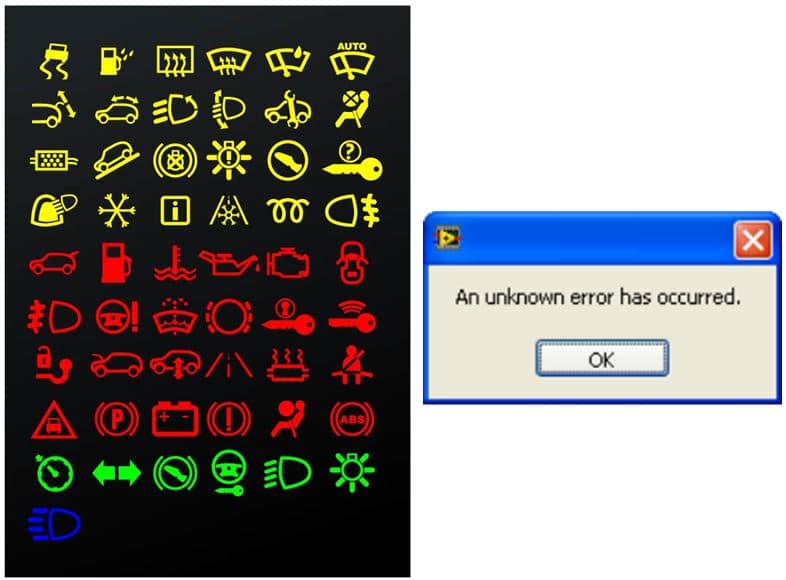
What do you do if, one morning, a new light with some strange symbol is suddenly lit on your car’s dashboard? You probably pull over and start browsing the car owner manual. You may be a little worried. Did I do something wrong? Can I fix this myself, or does the car need to be serviced? How long will I need to survive without my car?
In the same way, your Tagformance, the RFID test system that you typically use every day may have a problem you need to solve. You may already be an experienced user, or maybe you have just recently started to work with the system. When a new error message pops up or you get unexpected measurement results, it’s just like with your car. What’s wrong? Should I contact Voyantic Technical Support?
The answer to the last question is yes. You should.
*‘No such thing as a stupid question’ is a common phrase with a long history, and it makes perfect sense to me. *
If you have a problem with anything, and there is a possibility to get it solved quickly by asking someone who can help you, why shouldn’t you? The one who asks the “stupid question” may be doing a service to everyone, including the vendor, by pointing out a visible improvement to the product.
Here are some more or less typical situations where you might wonder if you should contact the vendor or just carry on. Uncertainty: You are performing measurements that look nice and smooth, but deep down, you are still wondering whether the results are correct? Is there some bias in the device? Am I measuring the right way? By contacting Voyantic Technical Support, we can verify if the device is OK by comparing the reference tag measurement results with the same measurement setup. We can also measure your sample tags and give a second opinion of the results and maybe give pointers on what else you can measure from your tags.
Differences between sites: You may have a colleague in the next room or on the other side of the globe doing the same measurements that you are. The equipment may be the same, the setup may be identical, but still, your results don’t match completely. For example, you get a theoretical read range value of 11 meters, and your colleague measures 10 meters. One meter sounds like a lot, but is it after all? By looking at the measurement data, we can verify whether the difference is something to worry about, or if it fits into production variation and typical measurement accuracy. Other factors, such as temperature, may cause a difference. The effect of temperature is described in more detail in an Application Note, which can be downloaded here. While visiting the site, you may find other Application Notes worth reading too.
Missing features: Different Tagformance measurement options are enabled with the license file. We can create license files where any measurement option can be enabled for a given time. So, if you think that one or more options could be useful for your work, we can enable the option for a trial period. To name a few;
Scripter is a great tool to automate your daily measurement routines and reduce the human error from the results.
The Tagformance has two Application Programming Interfaces, APIs, that enable you to write your software that uses the Tagformance device. The LabVIEW API is a perfect match for LabVIEW users, and the DLL API serves users of other programming languages.
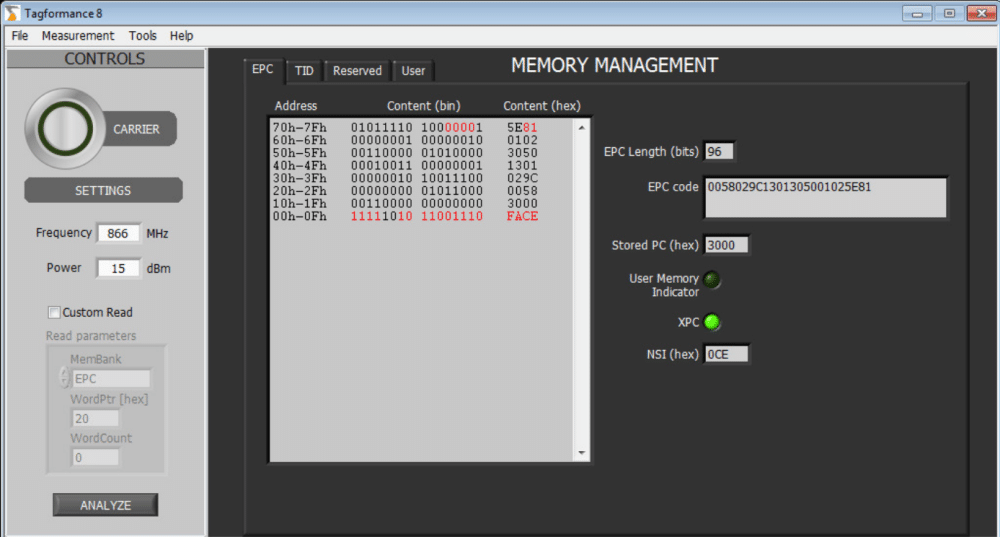
Memory management is a brand new tool for one of the hot topics, sensor tags, for example. With Memory management, it is possible to verify changes of any memory address content within seconds.
Memory Management
All this said, do not hesitate to contact us! In most cases, it is a win-win situation where you will get your problem solved or a question answered, and we get valuable feedback, which will help us in making our products even better. We are here to help you – send us a message!
"I enjoy seeing both Voyantic employees and our customers thrive. The grand majority of my time is invested in projects and initiatives that grow the RAIN RFID market in the long term. My remote office is on a patrol boat somewhere in the archipelago of Finland."
Content
What does EU tax harmonization, the war in Ukraine, and TIPP adoption have in common? All three appear to be stagnant battlefronts with plenty of hard work done behind the scenes but minor visible progress to outsiders. Is there something wrong with the world order, how to move forward? Relax, take a sip of Dr. Pepper and read on to see why and how TIPP will prevail.
What Do TIPP, Tire Sidewall Codes, and Automotive Oil Grades Have in Common?
TIPP is an acronym for Tagged Item Performance Protocol. The TIPP methodology was initially created in the USA to simplify and standardize the communication and accountability around RFID tagging. RFID tagging of retail items dramatically improves inventory accuracy. Without RFID, it is impossible to sustain accurate inventory, especially on the shop floor level, and without accurate inventory a retailer cannot effectively execute their omnichannel sales strategies.
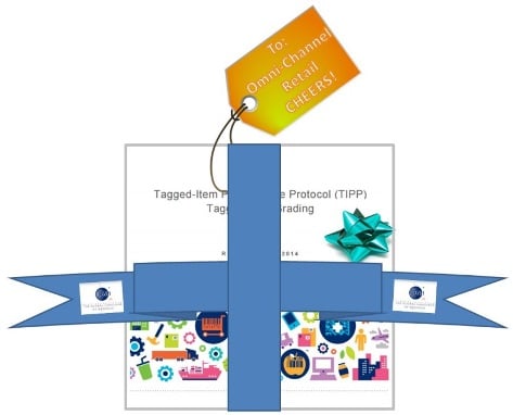
With this said, TIPP is a significant leap forward for any RFID adopting industry that looks to cut tagging costs, simplify communications, and clarify accountability. This approach would equally well serve the RFID adopters in the healthcare, automotive, and aerospace industries. It comes gift-wrapped by the GS1 US, too!
Little something for our friends!
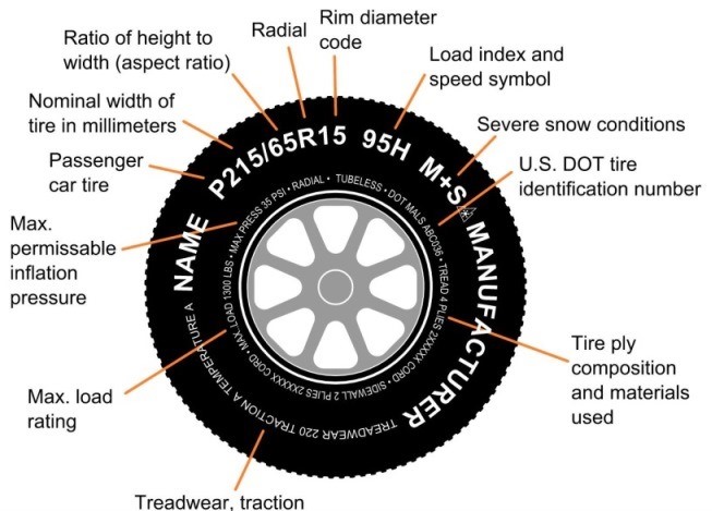
The TIPP approach bears an analogy to car tire codes. The standardized information on the tire sidewalls describes the fundamental characteristics of the tire and is mandated by US Federal Law and EU Directives. Adapting to this system, the car manufacturer carefully masters the product (car) design, sets the tire requirements with a few alternative sizes that the car owners then follow. Periodically there is the unbiased 3rd party to check that a particular car has tires that meet the specs, are not damaged nor too worn out. In all these technical affairs, the tire manufacturer’s responsibility is to come up with the numbers and put them on the product. The tire brand is devoted to the sales and marketing side of things.
I will take a second example also from the automotive industry: SAE oil grades. Most car makers don’t endorse Total, Shell, nor Valvoline above others, but simply specify multigrade SAE 5W-30 in the owner’s manual, perhaps with little twists as BMW-LL-04. These grades have temperature-viscosity built-in, which makes a real difference up here in the North Pole. This valuable classification work was done by the Society of Automotive Engineers – SAE, which also has set standards on the quality side. SAE oil grades lay the grounds for easy purchasing, healthy competition, and results in fewer engine problems for us all. In this setup, the oil brands play an important role that is simply fenced off from the underlying oil grading system.
These two examples illustrate how grading systems have made two major industries more transparent, efficient, and streamlined. Sure it took years to develop and enforce these common practices, but the outcome benefits everyone.
Maintaining Approved Inlay Lists Becomes Too Complicated as RFID Tagging Expands to New Product Categories
Before the TIPP was established, the early adopters of RFID came up with their ways of getting tagging done in a controlled manner. Often this meant countless hours of the trial-and-error type of testing, and the outcome in many cases was lists of approved inlays that are suited for a particular product category. Suppliers were then instructed to use inlays from those lists, and just for a while, the process seemed to be alright.
Gradually the pain started to manifest itself. Because an inlay product is in constant evolution, maintaining of inlay lists often turned out to be quite a burden. To make the situation even more uncomfortable, the amount of testing is dramatically increasing as RFID tagging expands to new product categories. Even suppliers were unhappy due to extra effort and expense because conflicting lists from different retailers lead to exception tagging.
Adopting TIPP Is Evident, But There Are a Few Speedbumps Left on The Road
GS1 US did a fantastic job in pulling retailers, suppliers, and RFID industry experts together, and as an outcome, the TIPP grading system with eight initial performance grades was introduced in January 2015. The test methodology was documented on the protocol, physical and practical levels. A logical and well-documented alternative to the approved inlay list processes had been introduced.
The TIPP Guideline also includes grades for stacked retail items.
So why is it that the US retail’s giants did not instantly adopt TIPP? I would list four factors:
The TIPP grades are not intuitive – which one to pick, and what to do if none of the eight alternative grades meet the read scenario requirements;
How to verify for the TIPP grades – RFID technology vendors have not yet introduced routine validation methods for TIPP graded retail items;
Many retailers are managing global supply chains, and they would rather adopt a global standard around RFID tagging;
From the perspective of a multi-billion dollar retail company, slowness is an integral part of “instant”.
All these issues can and will be resolved; it just takes time. The road ahead is, therefore, paved with education, training, convincing, waiting, and politics. This rough terrain is nothing new since most RFID vendors are ideally used to it already for a decade.
The Industry Is Multitasking And Making Further Progress
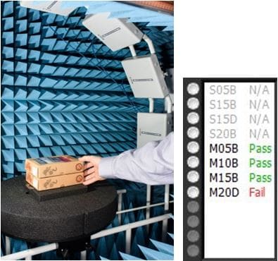
The vital steps that technology vendors and GS1 should take include making the TIPP grades more understandable, adding new grades in the portfolio, and introducing validation methods. All these issues are being addressed as we speak. In fact, for validation, there are already the first out-of-the-box solutions available, as you can see from the videos below.
On top of this great news, the GS1 Global Office is making a strong effort to develop a TIPP global standard. Retailers in the US, Europe, and Asia should all contribute and support GS1 in getting the global standard out promptly.
All this takes time. Many stakeholders are working on it, and it’s going to turn out great. Please contact me (juho.partanen@voyantic.com) for further insight!
Please accept marketing cookies to watch this video.
I am the CEO and co-founder of Voyantic, a company that specializes in RFID test and measurement solutions. Before starting Voyantic in 2004, I worked as a researcher at the Helsinki University of Technology focusing on passive RFID sensing for moisture in building structures.
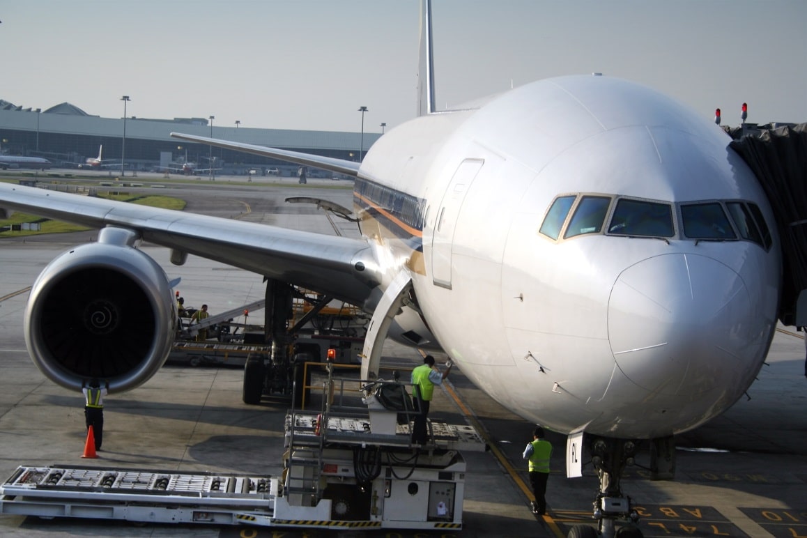
Retail RFID seems to get the most limelight in the RFID industry at the moment. And that is not surprising because of its huge tag volumes and growth rates. But many other sectors are benefiting from RFID use as well. One of my personal favorites is the aerospace industry.
The aerospace industry has been one of the pioneers in UHF RFID use
The most visible aerospace company in the RFID space has been Airbus. Their announcement, at the beginning of this year, to ask their supply base to tag all traceable items with passive RFID shows that they are serious. But also Boeing and Embraer come across regularly in RFID related news. To serve this industry, an ecosystem of RFID technology providers has emerged. Companies such as Fujitsu, Maintag, Tego, OAT Systems, and Brady, to name a few, have a special focus in aerospace RFID. Besides, the ecosystem has generated business opportunities for the supporting industry, see, for example, the Stanley Black & Decker success story.
What is Required from RFID in Aerospace?
So why are some RFID companies specializing in the aerospace industry? Can’t we just buy a roll of RFID labels and start tagging airplane parts? Well, it is not quite as simple as that. Several aspects set aerospace RFID, apart from many other application areas:
Large memory required: The aerospace industry requires that a lot of information (birth records, maintenance records, etc.) is stored directly into the tag. They don’t want to rely on a connection to an external database which is usually used in retail RFID.
Valuable items: The tagged items are of high value and are often used for ten years and more. As a result, tag durability is more important a driver than tag cost.
Harsh conditions: Tags in and out of an airplane need to endure vibration, significant variations in temperature, humidity, and pressure, and many other conditions unfamiliar to retail applications.
Global functionality: As airplanes frequently cross country borders and oceans, the RFID tags need to be readable around the world. As a result, the tags must be designed to be wideband.
Less sensitive tag ICs: Due to their larger memory content and possible special functionalities, the tag ICs used in aerospace typically need more power. As a result, many applications are limited to read ranges of 15 cm to 3 meters.
A Need for Standards
The aerospace industry realized that they need standardization for flyable tags as early as 2006. That is when a group of experts in the field decided to develop a standard under SAE International. SAE AS5678, “Passive RFID Tags Intended for Aircraft Use” was born. The standard includes a broad set of different environmental tests to make sure that a tag would endure the harsh conditions of a flying airplane. Sun APT Test Center was the first lab to start certifying tags according to the standard.
In addition to environmental testing, the standard also describes RF performance tests for the tags. The standard described a very professional and well repeatable measurement methodology. But even more interestingly, the standard divided tag performance into performance grades, somewhat similar to what the GS1 TIPP standard would do for the retail industry in 2015.
AS5678 was truly ahead of its time.
As a result, an airplane manufacturer could simply require a grade B tag to be used by its suppliers without having to specify the tag model or detailed performance parameters.
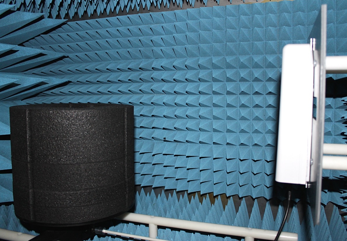
AS5678 performance tests are typically performed in a small anechoic chamber
Now, in 2015, SAE is revising the AS5678 standard to reflect the new information gained during the years. I have been a member of the team, revising the standard as well. The changes, however, are not very large, which well reflects the quality of the first standard version.
Specific RFID Testing Needs of the Aerospace Industry
The special requirements of the aerospace industry for RFID lead to some specific testing needs:
Measuring tag performance: Because of the large memory contents, wide bandwidth, and rugged design, aerospace tags may have limited read ranges. The AS5678 test methodology can be used to determine the acquired read range and the matching performance grade.
Verifying tag bandwidth: Since a wide bandwidth is required, the performance of the tag needs to be tested typically throughout the 860-960 MHz frequency range.
Environmental tests: AS55678 describes a large set of environmental conditions that the tag needs to endure. The performance of the tag should not degrade during the tests.
Memory testing: The memory of an aerospace tag is organized differently compared to a typical label. As a result, there is a need to have good visibility to the tag memory contents.
My company Voyantic has delivered test and measurement systems for both end-users and technology providers in the aerospace RFID industry. The systems promote design and manufacturing excellence, as well as fluent technical dialogue between pioneering companies within the industry.
If you are interested to learn more, please download our application note below or contact us, and let’s talk more!
Learn How to Test UHF RFID Tags in the Aerospace Industry
Download The Essential Guide for UHF Tag Testing in Aerospace
I am Sales Director at Voyantic. I have over 15 years of experience from the RFID industry in Europe and the USA. I have two master's degrees: in industrial engineering and in marketing, and two patents in auto-ID technology. I am actively participating in RAIN RFID alliance activities.
Content
ISO 18000-63 (6C, EPC Class 1 Gen 2) has been by far the most used UHF RFID standard for several years. There have been some competing standards such as Tagidu, IP-X (tag-talks-only), and ISO18000-62 (6B), but they are nowadays rarely used in new applications. However, new RFID standards still emerge: for example, in Brazil, SINIAV has created a protocol aimed for vehicle tracking applications. In China, a new UHF standard, GB/T29768-2013, has been recently published.
Several tag manufacturers work with these new standards. Why do these national RFID standards exist? And what does it mean for performance testing?
Why Doesn’t Everyone Work with the Same Standard?
Since there is a well-working global standard, it would sound logical to use it for as many applications as possible. But there are some reasons for using something else as well. There may be national interests, or maybe there are special requirements that existing standards don’t cover well enough. For example, ISO 18000-63 was developed for quickly inventorying large quantities of items, and it may not be optimal for reading a single tag that is passing by at 180 km/h. Another challenge may be when the tag is in the windshield of a truck filled with other tagged items.
It should also be noted that the division to separate standards does not always have to be final. Commonly, new functionalities and exclusive features are absorbed into the global standard after they are validated.
What is the Difference Between the Different Standards?
When we talk about passive UHF RFID, we talk about readers that radiate between 860 to 960 MHz to power up remote tags, which in turn modulate their reflection to communicate back to the reader. That is common between all passive UHF RFID standards.
The difference is in how the readers and tags modulate the electromagnetic waves, and what kind of command and response sequences are used in the communication.
One standard might be optimized for quick inventorying while another might provide added security.
Besides, the complexity of the protocol affects the power consumption of the chip and, thus, the read range that can be acquired.
What do the National Standards Mean for Tag Manufacturers
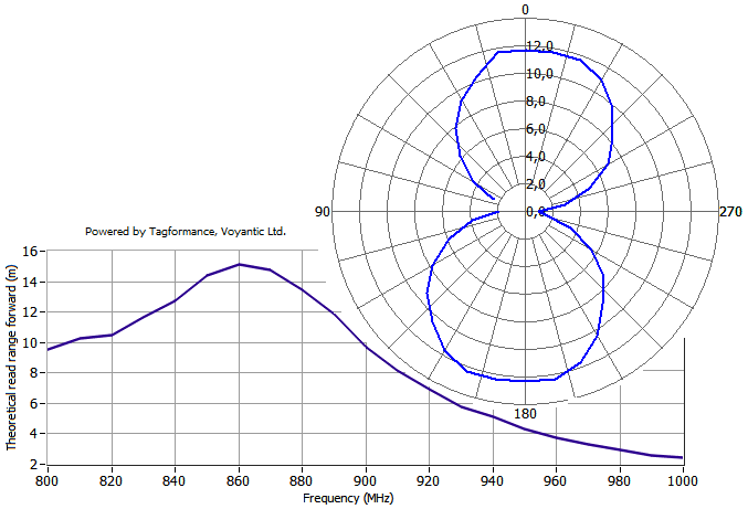
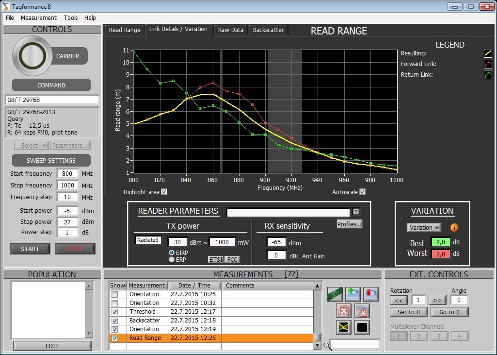
So how should a tag manufacturer respond to a customer’s request to make a tag for a less widely used UHF RFID standard? Well, that depends on the opportunity. But there is nothing to be afraid of in the design process – it is no different from ISO 18000-63 tags. The Voyantic Tagformance system supports performance testing of the GB and SINIAV protocols (as well as older ISO 18000-62 and IP-X protocols).
With the Tagformance system, it is quick to characterize a UHF RFID tag regardless of the protocol: just choose which protocol is to be used in testing and then start the selected test. Results include (but are not limited to) information about the tag sensitivity, read range, tuning, and radiation pattern.
Application Developers
New RFID standards are often used in new application areas. With the Voyantic’s Field Engineer’s Kit, RFID tags can be tested within the application – for example, when attached to a vehicle. Vehicles are an example of a quite challenging environment for RFID because of their large metal parts and a variety of different plastic and glass types where tags are mounted. Thus, field test results are crucial.
Typical field tests aim to verify the read range. The Tagformance system can be used in evaluating what kind of read range can be achieved with different readers – without actually using the readers. Based on the tag measurements and the reader information input by the reader, the system shows the achievable read range, but also which tag or reader parameter is the bottleneck for system performance.
Download the Tagformance Pro Catalogue
Learn more about the Voyantic Tagformance® Pro Test Device! By combining RAIN RFID and NFC testing into one compact test device, our all-new Tagformance Pro is a true all-in-one tool for anyone either developing or using RFID technology.


